v When the rails are fully extended, the rail safety latches lock into place. This action prevents the
system from being pulled out too far.
Procedure
1. Label and remove all cables from the rear of the system.
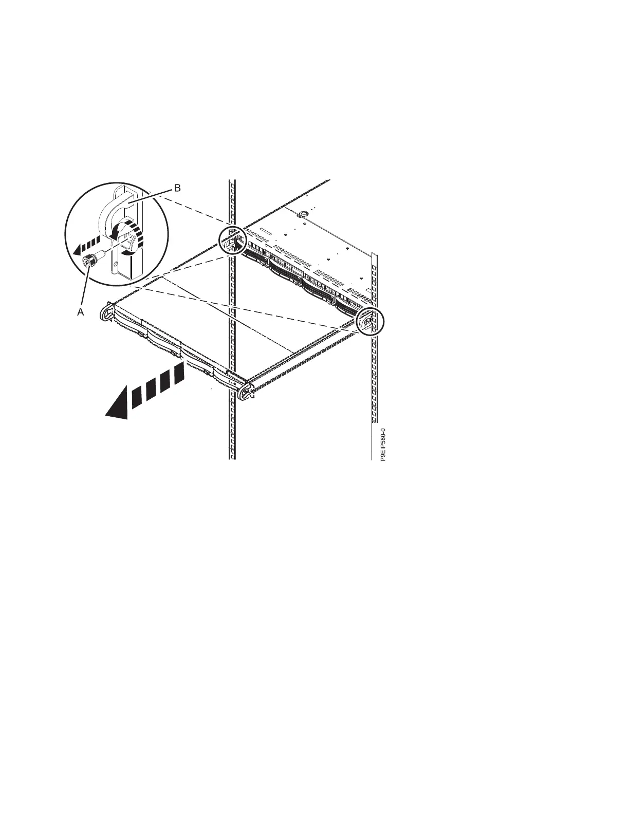
2. Remove the front screws (A) that secure the system to the rack from both sides of the system as
shown in Figure 69.
3. Pull the system unit out of the rack.
CAUTION:
v The chassis rails only extend about half of the distance of the chassis. Once the safety latches
are released, the chassis only slides forward a few inches before disengaging from the rails. Be
prepared to support the full weight of the chassis as you remove it from the slide rails.
v The chassis contains most of the weight in the back side of the unit. When you remove the
system, take care to be ready to support the weight by grasping the chassis closer to the back of
the unit.
4. Using two people, release the rail safety latches and remove the system from the rails. The safety
latches work in opposite directions; the latch on one side moves up while the latch on the other side
moves down.
5. Carefully set the system on a table with an appropriate ESD surface.
Placing a 7063-CR1 system into the operating position
Learn how to place an IBM 7063-CR1 Hardware Management Console system into the operating position.
Figure 69. Removing the front screws and removing the system from the rack
78 Power Systems: Servicing the 7063-CR1 Hardware Management Console system
 Loading...