11. From the bottom of the processor assembly lift the side access cover. The cover is
held to the top of the processor assembly by four hinges. Pivot the cover up to
reveal the memory DIMMs or DIMM connectors.
12. Remove all memory DIMMs as described in “Memory DIMM Removal” on
page 113. Put the DIMMs in a safe place, you will need to install these DIMMs
onto the new processor card.
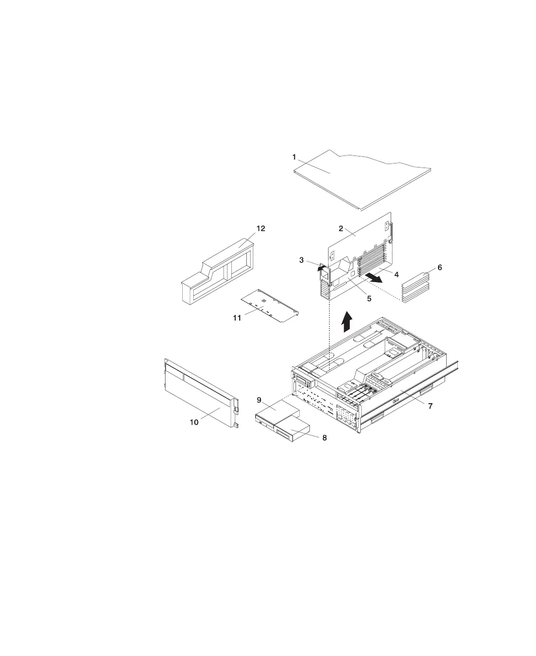
1 Service Access Cover 7 Model 6C4
2 Processor Access Cover 8 Optional Media Device (for
example: Diskette Drive or
Tape Drive)
3 Processor Cage Lifting and
Release Handles
9 IDE CD-ROM Drive
4 Processor Assembly 10 Front Bezel
5 Processor Card 11 Media Device Support Shelf
6 Memory DIMMs 12 Processor Filler
Chapter 4. Installing Options
109
 Loading...


