Covers
Before performing the following procedure, read the “Safety Notices” on page vii.
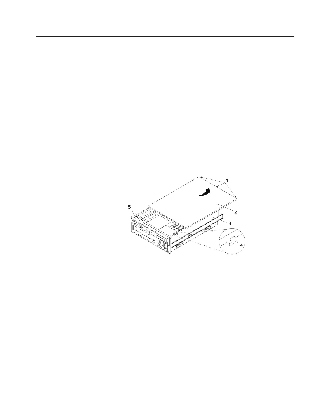
Service Access Cover Removal (Model 6C4)
To remove the service access cover, do the following:
1. Ensure the rack has been correctly stabilized before opening the front and rear rack
doors.
2. Open the front rack door and place Model 6C4 into the service position as
described in “Placing the Model 6C4 into the Service Position” on page 53.
3. Loosen the three captive thumbscrews located on the rear of the cover. See the
following illustration for thumbscrew locations.
4. Placing both hands on each side of the cover, slide the cover toward the rear of the
system drawer. After the front of the service access cover has cleared the upper
chassis ledge, lift the cover up and off the system drawer.
Attention: For proper cooling and airflow, replace the cover before turning on the
system. Operating the system for extended periods of time (over 30 minutes) with the
cover removed might damage the system components.
1 Thumbscrews 4 Access Cover Locking Tab
2 Service Access Cover 5 Upper Chassis Ledge
3 Model 6C4
Service Access Cover Replacement (Model 6C4)
To replace the service access cover, do the following:
1. Align the service access cover with the top of the system, about 25 mm (1 inch)
from the front of the system. The flanges on the left and right sides of the cover
should be on the outside of the system chassis.
2. While holding the service access cover against the system drawer, slide it toward
the front of the system. The front edge of the service access cover should slide
beneath the upper chassis ledge.
3. Tighten the three thumbscrews located on the rear of the cover.
Chapter 4. Installing Options 55
 Loading...


