Appendix D. Fault and Attention LEDs
This appendix contains information about fault and attention LEDs, which assist in
identifying failing components in your system.
Operator Panel Display
If a failing component is detected in your server, an amber-colored attention LED is lit.
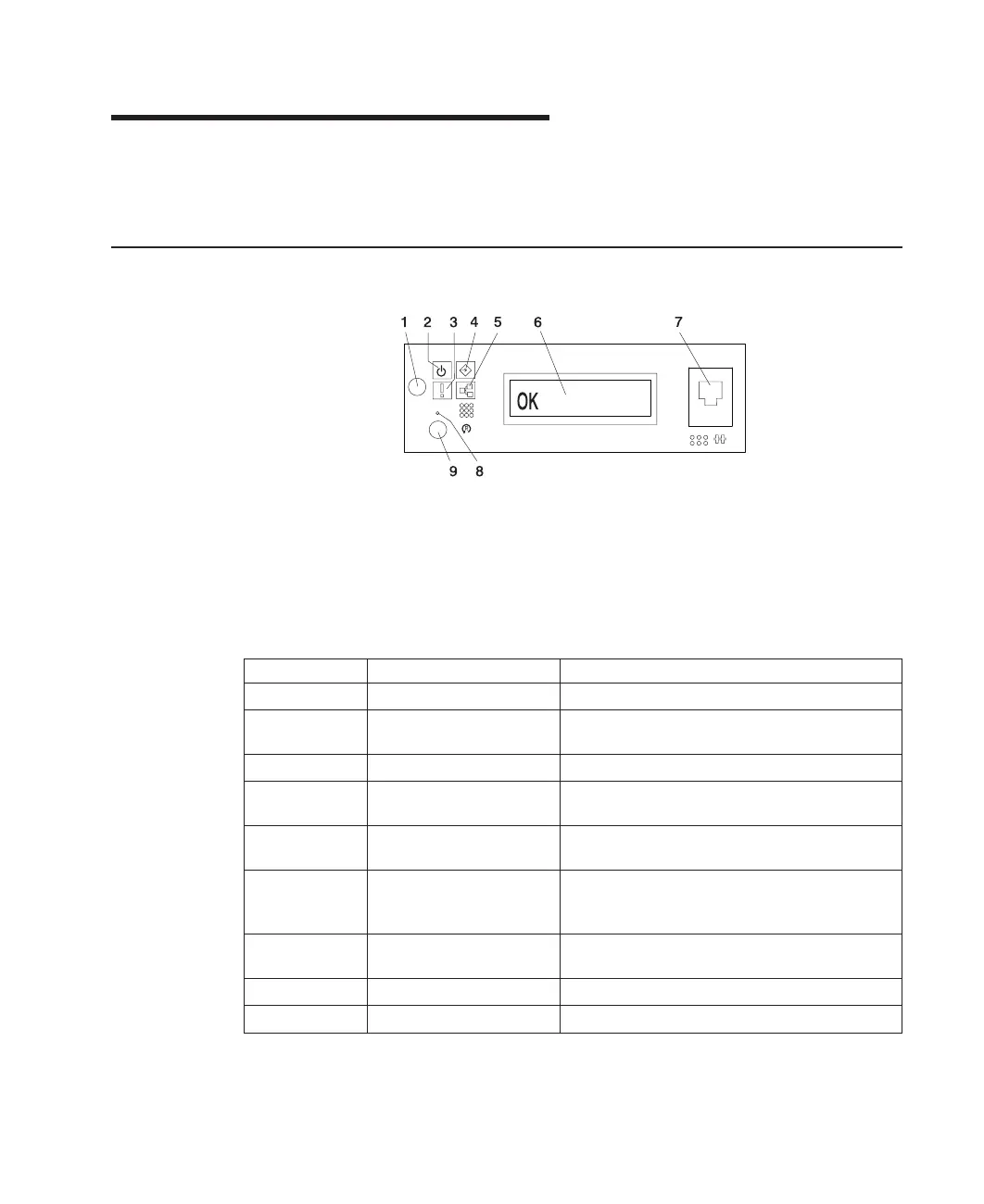
1 Power-On Button 6 Operator Panel Display
2 Power LED 7 (FS1) Front Serial
Connector (RJ48 Connector)
3 Attention LED 8 CSP Reset Button (Pinhole)
4 SCSI Port Activity 9 System Reset Button
5 Ethernet Port Activity
Number Component Name Component Description
1 Power-On Button Turns the system power on and off.
2 Power LED Normal State - LED is on when system is
connected to a power source.
3 Attention LED Normal State - LED is off.
4 SCSI Port Activity Normal State - LED is on when there is SCSI
activity.
5 Ethernet Port Activity Normal State - LED is on when there is Ethernet
activity.
6 Operator Panel Display Displays current status of system startup, or
diagnostic information in the event of a hardware
problem.
7 Front Serial Connector
(FS1)
Serial port uses RJ48 connector. Use to plug in
external devices at the front of the system unit.
8 CSP Reset Button Service Personnel Use
9 System Reset Button Resets the system
141
 Loading...


