Notes:
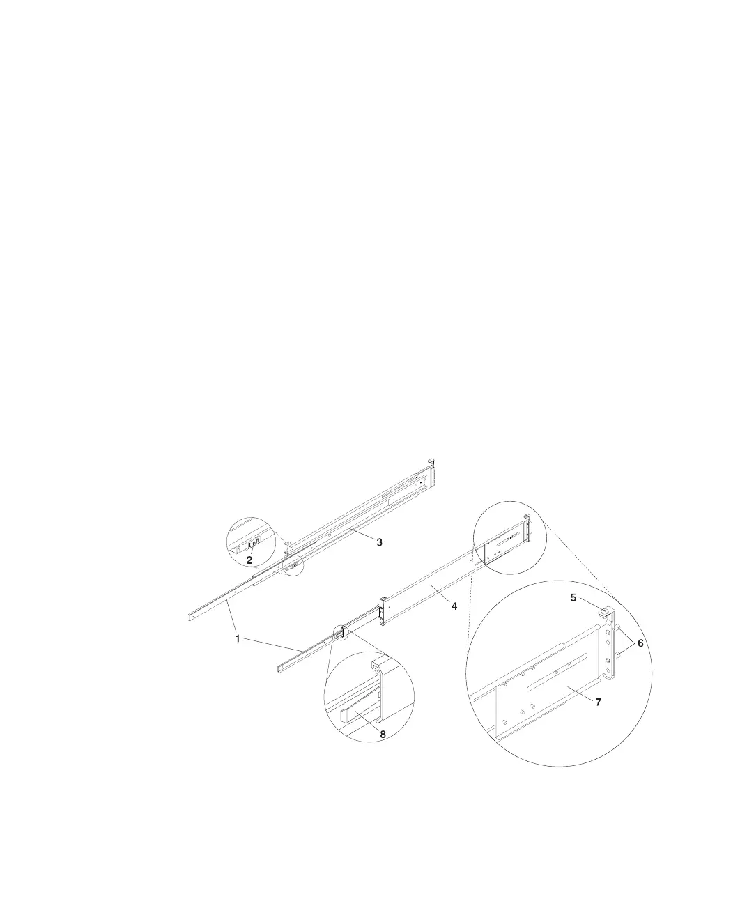
a. The system rails are front-to-back and left-to-right side dependent when you
are standing in the front of and facing the rack. The rails are labeled on the
front lower corner, left or right. The back of the rails can be identified by the
two large alignment pins and the rail-length adjusting plate. The top of the rails
can be identified by the screws located on the top of the front and rear rail
flange. See the following illustration.
b. The rack-mounting hardware kit has 4 changeable rail brackets and 2 sets of
alignment pins. If the alignment pins that came assembled to the rails do not fit
your rack, remove the brackets from the rails. To remove the alignment pin
bracket from each of the rails, do the following:
1) Remove the screw located on top of the rail bracket assembly.
2) Slide the top of the alignment pin bracket from beneath the front-rail
bracket.
3) Lift the bottom tab out of the front-rail bracket slot.
After determining the correct size alignment pin to use, mount them onto the
replacement brackets and install them onto your rails. Rail bracket assembly is
the reverse of the removal procedure.
c. Always mount the brackets containing the short alignment pins onto the front of
the rail.
1 Left and Right Inner Rails 5 Top-Rail Flange Screw (Rear)
2 Left Rail Label 6 Rear-Rail Alignment Pins
3 Left Rail Assembly 7 Rail-Length Adjusting Plate
14 Eserver
pSeries 630 Model 6C4 and Model 6E4 Installation Guide
 Loading...


