Installing drives
The following notes describe the type of drives that the server supports and other
information that you must consider when you install a drive. For a list of
supported drives, see http://www.ibm.com/systems/info/x86servers/
serverproven/compat/us/.
v Locate the documentation that comes with the drive and follow those
instructions in addition to the instructions in this chapter.
v The server supports one optional ultra-slim SATA CD-RW/DVD-ROM optical
drive.
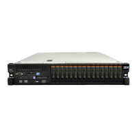
v The server can support up to sixteen 2.5-inch drives, up to thirty-two 1.8-inch
drives, or a combination of both 2.5-inch and 1.8-inch hot-swap drives, using the
supported SAS/SATA backplane configurations. The server supports 2.5-inch
hot-swap SAS or hot-swap SATA hard disk drives, 2.5-inch hot-swap SATA solid
state drives, and 1.8-inch hot-swap SATA solid state drives (see “Supported
SAS/SATA drive backplane configurations” on page 53 for more information).
v You can mix 2.5-inch hot-swap SAS and SATA hard disk drives, 2.5-inch
hot-swap SATA solid-state drives, and 1.8-inch hot-swap SATA solid-state drives
in the same server as long as you use the same type of drives within the same
array.
v When you upgrading drive backplane configurations, you must install all
1.8-inch solid state drive backplanes to the right of all 2.5-inch hard disk drive or
2.5-inch solid state drive backplanes. All 2.5-inch backplanes must be installed to
the left of all 1.8-inch backplanes. See “Drive IDs” for drive ID assignment
information and “Supported SAS/SATA drive backplane configurations” on
page 53 for information about the combination of supported drive backplane
configurations.
v The 8x2.5-inch hot-swap drive backplane with controller expander must always
be installed in backplane bays 3 and 4. See “Connecting the SAS cables” on page
61 for more information about cabling the SAS cables.
v The electromagnetic interference (EMI) integrity and cooling of the server are
protected by having all bays and PCIe slots covered or occupied. When you
install a drive, save the EMC shield and filler panel from the bay in the event
that you later remove the device.
Drive IDs
The hot-swap-drive ID that is assigned to each drive is printed on the front of the
server. The following illustrations show the locations of the IDs of the drives. The
ID numbers and the drive bay numbers are the same.
Note:
1. The drive bay IDs can vary, depending on the combination of the SAS/SATA
backplanes installed in the server.
2. When upgrading drive backplane configurations, you must install all 1.8-inch
solid-state drive backplanes to the right of all 2.5-inch hard disk drive or
2.5-inch solid-state drive backplanes. All 2.5-inch backplanes must be installed
to the left of all 1.8-inch backplanes.
3. If you install a 8x1.8-inch drive backplane assembly, the drive IDs that are
indicated on the server front bezel will no longer be valid. Use the drive labels
that come with the backplane to renumber the drive IDs on the bezel.
Chapter 2. Installing optional devices 51
 Loading...