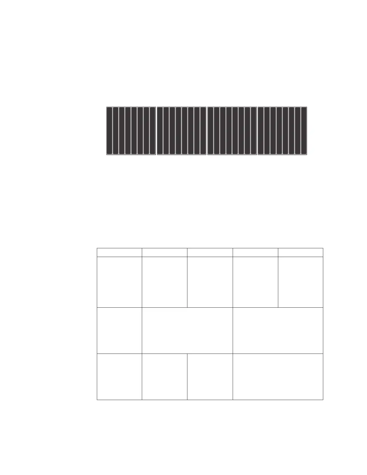
Backplane configuration for 32 drives
This information describes the supported backplane configuration for 32 drives.
About this task
The following illustration shows the supported backplane configuration to support
32 drives.
This configuration consists of four 8x1.8-inch drive backplanes and requires
eight SAS signal cables.
1.8” SSD
1.8” SSD
1.8” SSD
1.8” SSD
1.8” SSD
1.8” SSD
1.8” SSD
1.8” SSD
8 9 10 11 2120 22 23
1.8” SSD
1.8” SSD
1.8” SSD
1.8” SSD
1.8” SSD
1.8” SSD
1.8” SSD
1.8” SSD
1312 14 15 1716 18 19
1.8” SSD
1.8” SSD
1.8” SSD
1.8” SSD
1.8” SSD
1.8” SSD
1.8” SSD
1.8” SSD
0123 5467 2928 30 31
1.8” SSD
1.8” SSD
1.8” SSD
1.8” SSD
1.8” SSD
1.8” SSD
1.8” SSD
1.8” SSD
2524 26 27
Connecting the SAS cables
This section provides information on how to connect the SAS cables to the drive
backplanes.
About this task
The following table provides information for connecting the SAS cables to the
drive backplanes (BP) based on the backplane slot and supported drive backplane
configurations:
Table 15. Connecting the SAS cables to the drive backplanes (BP) based on the
configurations
Drive backplane BP 1 BP 2 BP 3 BP 4
4x2.5-inch drive
backplane
v Connect the
SAS cable
from BP 1 to
the SAS signal
connector port
0onthe
system board.
v Connect the
SAS cable
from BP 2 to
the SAS signal
connector port
1onthe
system board.
v Connect the
SAS cable
from BP 3 to
port 0 on the
PCIe adapter.
v Connect the
SAS cable
from BP 4 to
port 1 on the
PCIe adapter.
8x2.5-inch drive
backplane
v Connect one SAS cable from BP
1 to the SAS signal connector
port 0 on the system board.
v Connect one SAS cable from BP
2 to the SAS signal connector
port 1 on the system board.
v Connect one SAS cable from BP
3 to port 0 on the PCIe adapter.
v Connect one SAS cable from BP
4 to port 1 on the PCIe adapter.
8x2.5-inch drive
backplane with
controller
expander
v Connect one SAS cable from BP
3 to the SAS signal connector
port 0 on the system board
v Connect one SAS cable from BP
4 to the SAS signal connector
port 1 on the system board
64 System x3750 M4 Types 8722 and 8733: Installation and Service Guide
 Loading...