3-1
• RF CIRCUITS
• LPF TABLE
SECTION 3
CIRCUIT DESCRIPTION
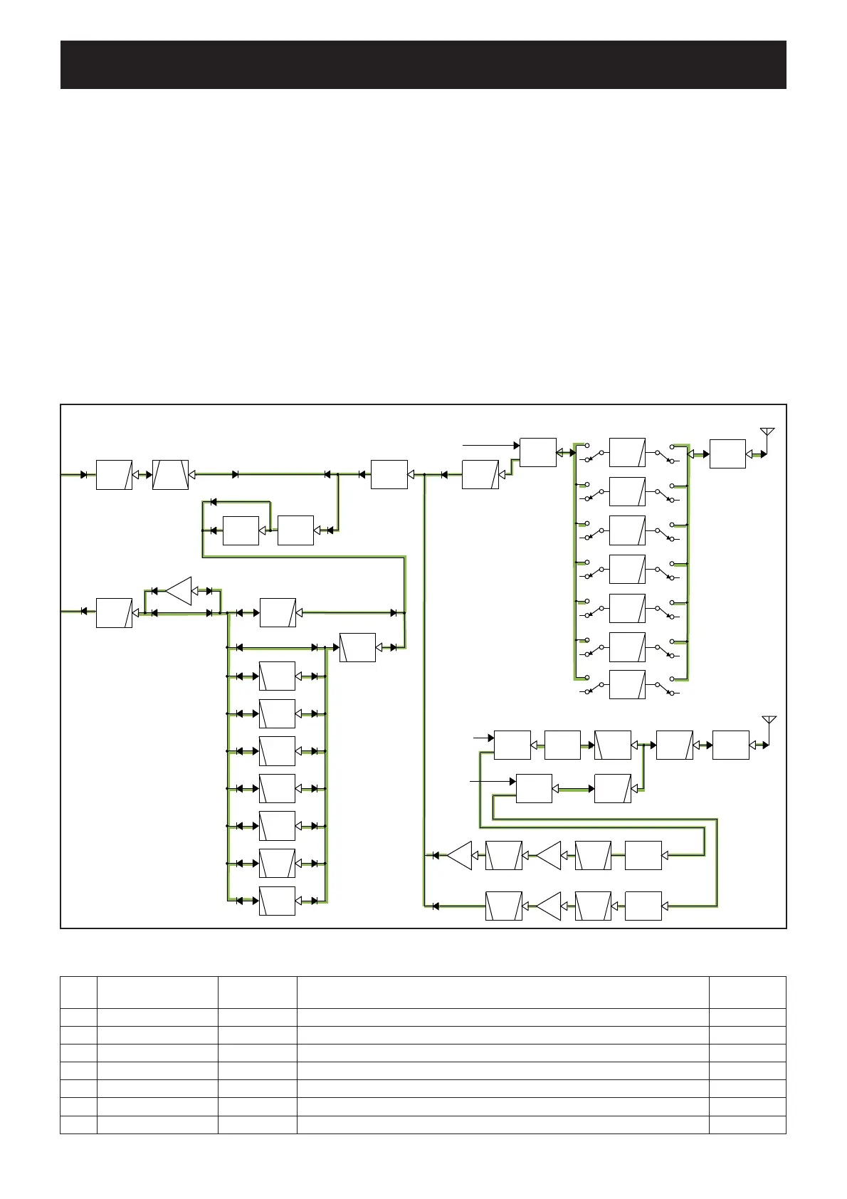
3-1 RECEIVER CIRCUITS
RF CIRCUIT (PA UNIT)
• While operating on the HF, 50 MHz and 70 MHz bands
The RX signal from the antenna connector ([ANT1]: J1) is
passed through the power/SWR detect circuit (D961 and
D962) and one of the LPFs, depending on the operating
band, to remove unwanted out-of-band signals. (See the LPF
TABLE below.)
The fi ltered RX signal is passed through the TX/RX SW
(RL801) and LPF (L801, L802, C801, C803 and C805) for fur-
ther removal of unwanted signals, and then passed through
the mute SWs (D181 and D182).
When the attenuator is turned ON, the RX signal is passed
through the 18 dB attenuator (
MAIN UNIT: D3082 and D3083).
The RF signal is passed through one of the BPFs, depend-
ing on the operating frequency, to remove unwanted signals.
(See the BPF TABLE on page 3-2.)
The fi ltered signal is applied to the pre-AMP circuit.
PRE-AMP CIRCUIT (MAIN UNIT)
When the pre-AMP is turned ON, the RX signal is amplifi ed
by the pre-AMP (Q3201).
The amplifi ed signal is applied to the 1st RX IF circuits.
LPF
BPF
LPF
“L1”
“L2”
“L3”
“L4”
“L5”
“L6”
“L7”
D961,D962
PWR/SWR
DET
TX/RX
SW
ATT
BPF
TX/RX
SW
LPF
HPF
TX/RX
SW
ANTENNA
LPF
ANTENNA
BPF
LPF
PWR/SW R
DET
LPF
LPF
MUTE
LPF
LPF
ATT
LPF
PRE
AM P
RF
AM P
PRE
AM P
BPF
MUT E
144 MHz band
7.3-14.35MHz
430 MHz band
fc=270M
fc=74.8MHz
From the TX circuit
PA UNIT
fc=200M
21.45-33.0MHz
14.35-21.45MHz
fc=700M
144/430MHz
430 MHz
HF/50MHz/70MHz
144 MHz
0.03-2.0MHz
2.0-4.0MHz
4.0-7.3MHz
33.0-74.8MHz
(74.8-200 MHz)
(74.8-200MHz)
D181,D182
Q481
Q451
Q551
D422,423,424
D433,D434
D651,D661
(400-470 MHz)
(400-470MHz)
20dB
20dB
HP
F
LPF
MUT E
D3072
HP
F
BPF
ATT
BRF
HPF
HP
F
LPF
“B1”
LPF
HP
F
HP
F
PRE
AMP
Q3201
HPF
13.9-20.9MHz
f c=500MHz
1.6-2.0MHz
2.0-3.4MHz
6.9-13.9MHz
3.4-6.9MHz
0.03-1.6MHz
74.8MHz and below
74.8MHz or above
To the 1st RX IF circuit
(74.8MHz and below)
To the 1st RX IF circuit
(74.8MHz or above)
40.0-60.0MHz
1.6-74.8MHz
60.0-74.8MHz
18dB
20.9-40.0MHz
fc=74.8MHz
D3272
“B2”
“B3”
“B4”
“B5”
“B6”
“B7”
“B8”
“B9”
From the
TX circuit
From the
TX circuit
Filter
Operating frequency
(MHz)
Filter switches
Components
Control line
(Active High)
L1
0.030000 to 1.999999
RL880 RL881 L881, L882 C882 to C886, C888 to C890, C893, C894, C896, C897, C899 L1
L2
2.000000 to 3.999999
RL920 RL921 L921, L922, C922 to C929, C933, C984 L2
L3
4.000000 to 7.300000
RL840 RL841 L841 to L843, C842 to C848, C850, C854 to C859 L3
L4
7.300001 to 14.350000
RL900 RL901 L901 to L903, C902, C907 L4
L5
14.350001 to 21.450000
RL940 RL941 L942, L943, C944 to C947, C950, C953 L5
L6
21.450001 to 32.999999
RL820 RL821 L822, L823, C824 to C828, C833, C835 L6
L7
33.000000 to 74.799999
RL860 RL861 L861 to L863, C863 to C866, C868, C869, C873, C875 to C878 L7
 Loading...


