4-1
SECTION 4
ADJUSTMENT PROCEDURE
4-1 PREPARATION
M REQUIRED EQUIPMENTS
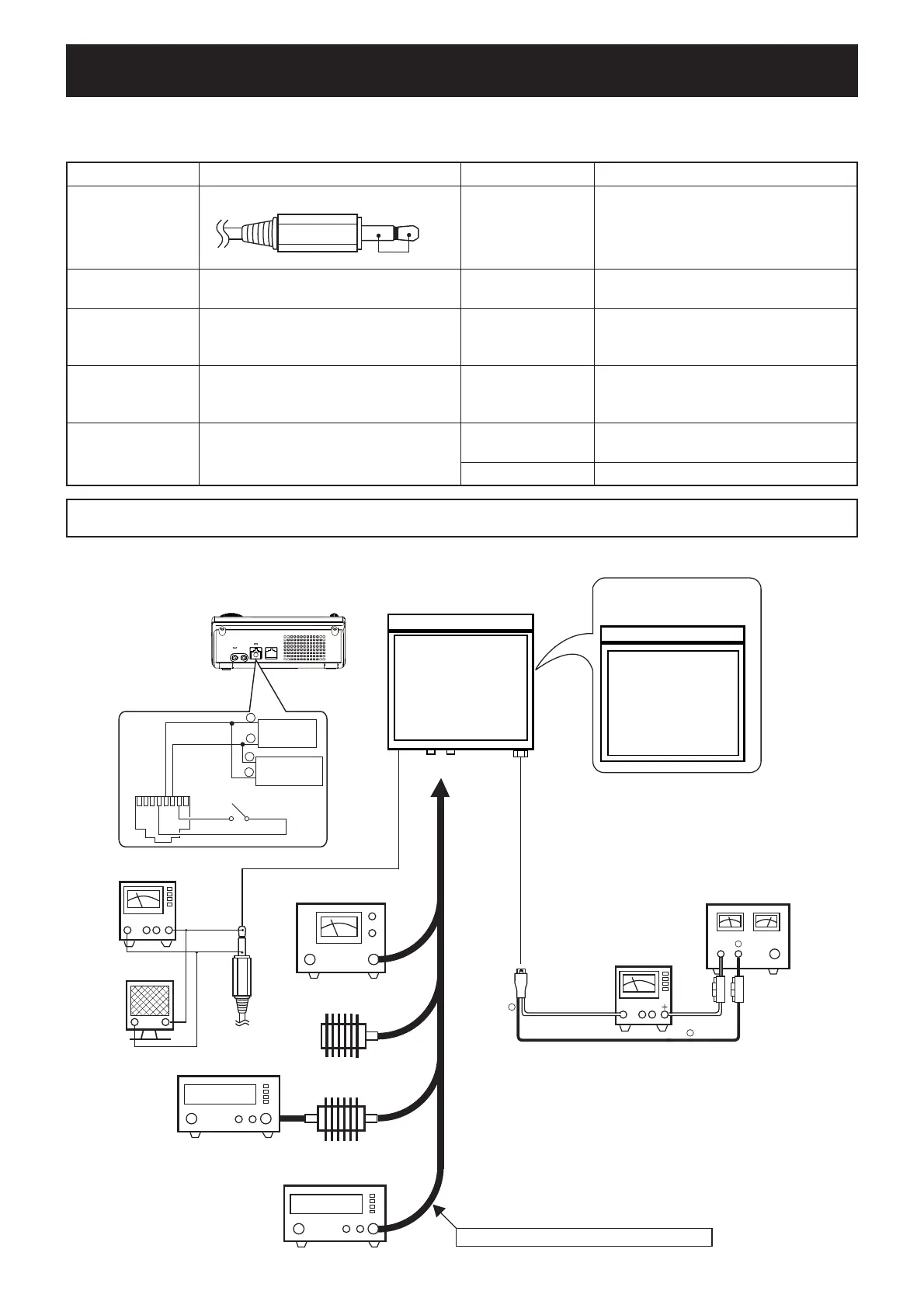
M GENERAL CONNECTION AND UNIT LOCATION
EQUIPMENT GRADE AND RANGE EQUIPMENT GRADE AND RANGE
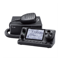
Short plug
Modifi ed 3.5 mm (1/8’’) monoral plug
Audio generator
(AG)
Frequency range : 300–3000 Hz
Output level : 1–500 mV
Output signal : sine wave
RF voltmeter
(50
Ω
terminated)
Measuring range : 20–200 mV
Frequency range : 0.1–600 MHz
AC Millivoltmeter Measuring range : 10 mV to 10 V
RF power meter
(50
Ω
terminated)
Measuring range : 5–120 W
Frequency range : 0.1–600 MHz
SWR : Less than 1.2 : 1
Multimeter
Measuring range : 0–10 V (Voltage)
1–30 A (Current)
Frequency counter
Frequency range : 0.1–600 MHz
Frequency accuracy : ±1 ppm or better
Input level : Less than 1 mW
External speaker
Input impedance : 8
Ω
Capacity : More than 2 W
Standard signal
generator (SSG)
Frequency range : 0.1–600 MHz
Output level : 0.1 mV to 32 mV
(–127 to –17 dBm)
Spectrum Analyzer
Frequency range : At least 90 MHz
Bandwidth : 100 kHz
Dummy Loads Impedance :
50
Ω
and 100
Ω
/120 W
CAUTION!:
SAVE the originally programmed contents
(Memory channel contents, set mode settings, etc.),
before starting
adjustment. When all adjustments are completed, these contents in the transceiver may be cleared.
[MIC]
[SP]
To the antenna connectors
[ANT1]/[ANT2]
<Viewing from the BOTTOM side>
PA UNIT
AC MILLIVOLT METER
(10 mV to 10 V)
EXT. SPEAKER
(2 W/8 Ω)
+–
+
–
<Viewing from
the TOP side>
MAIN UNIT
DUMMY LOAD
(50 Ω/120 W)
RF POWER METER
(120 W/50 Ω)
STANDARD SIGNAL GENERATOR
(0.1–60 MHz)
NEVER TRANSMIT while an SG is connected.
FREQUENCY COUNTER
(0.1–1 GHz)
ATTENUATOR
(40/50 dB/100 W)
[DC 13.8V]
AMMETER
(0.1–30 A)
Fuses
30 A
DC power supply
(13.8 V/30 A)
⊕
−
Black
Red⊕
Red⊕
−
Black
−
−
Supplied DC cable
Audio
generator
Pin 5
MIC GND
Pin 6
MIC INPUT
–
+
Pin 4
PTT
Millivoltmerter
18
Pin 7
GND
–
+
(Short)
 Loading...


