3-8
• LOCAL OSCILLATOR CIRCUITS
3-3
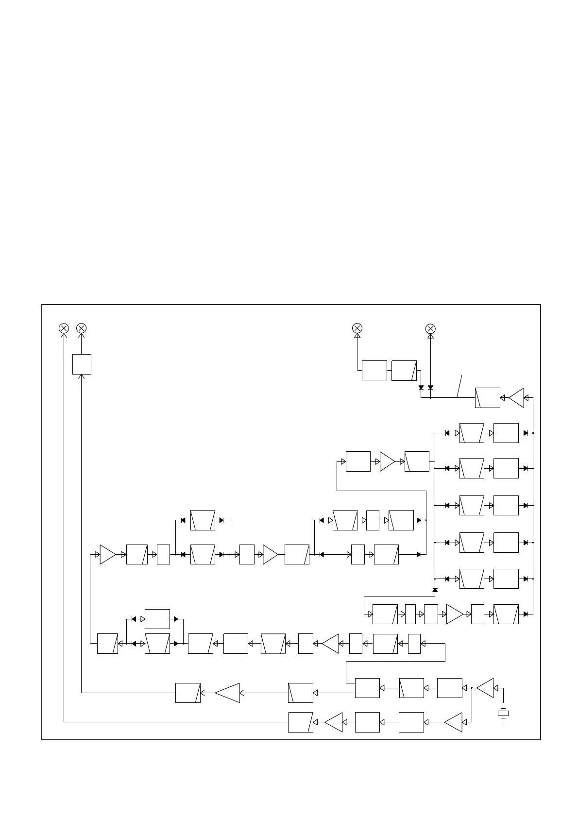
LOCAL OSCILLATOR CIRCUITS (MAIN UNIT)
REFERENCE FREQUENCY OSCILLATOR CIRCUIT
The crystal oscillator (X2001) generates the 41.344 MHz ref-
erence frequency signal. This reference signal is applied to
the Local Oscillator (LO) circuits, through the buffer (Q2001
and Q2002), and used as the reference clock signal of DDS
or the 2nd LO signal.
3RD TX/RX LO CIRCUIT
The 41.344 MHz reference signal from the crystal oscillator
(X2001) is amplifi ed by the buffer (Q2001 and Q2002) and LO
AMP (IC2001), and then divided into 1/4 (10.336 MHz) by the
divider (IC2003), resulting in the 10.336 MHz reference clock
signal. The clock signal is applied to the DDS (IC2002).
Using the applied signal as the reference clock, the DDS
(IC2002) directly generates the 491 kHz 3rd TX LO signal.
The 491 kHz 3rd TX LO signal is amplifi ed by the LO AMP
(Q2003), and passed through the LPF (L2004 and C2018),
and then applied to the 3rd IF mixer (IC4502).
2ND TX/RX LO CIRCUIT
The 41.344 MHz reference signal from the crystal oscillator
(X2001) is amplifi ed by the buffer (Q2001 and Q2002), and
then applied to the frequency multiplying circuit (Q2101),
which extracts the 3rd harmonic component, resulting in the
124.032 MHz 2nd LO signal.
The 124.032 MHz 2nd LO signal is passed through two HPFs
(L2103, C2105, C2108 and L2106, C2112, C2114) and split-
ter (L2104, L2105, C2110 and C2111), and then applied to
the LO AMP (Q2102).
The amplifi ed signal is applied to the 2nd IF mixer (D4301 and
D4302), through the LPF (L2109, L2110, C2119 to C2123)
and 6 dB attenuator (R4302 to R4304).
AM P
BPF
AM P
LPF
DDS
BPF
LPF
BPF
HPF
BPF
LPF
D3252,D3253
X2
SAW
BPF
X3
BPF HPF
SPLITER BUFF
D4301,D4302
BPF
“LOF1”
“LOF2”
“LOF3”
“LOF4”
“LOF5”
“LOF6”
1/4
ATT
AMP
BPF
DDS
X3AM P
BPF
ATT
ATT
ATT
ATT
ATT
ATT
X2 AM P
ATT AMP
X2
ATT
LPF
BPF
ATT
Q3231,Q3232
ATT
LPF
AM P
HPF
LPF
LPF
ATT
LO
AM P
LPF
LO
AMP
HPF
HPF
LPF
ATT
LPF
ATT
184.5-240.0 MHz
3LO
124.5-184.5MHz
124.5-154.5 MHz
6dB
124.032MHz
2LO
1LO
240.0-272.5 MHz
2LO
UHF: 524.487-594.487 MHz
272.5-324.5 MHz
31.125-81.125MHz
184.5-240.0MHz
419 kHz
ATT
4dB
124.032 MHz
HF/VHF: 124.517-324.487 MHz
3LO
154.5-184.5 MHz
419kHz
41.344 MHz
fc=500kHz
2dB
6dB
6dB
3dB
1st mixer
(VHF/UHF TX/RX and HF TX)
3rd mixer 2nd mixer
X2001
Q2001
Q2002
Q2101
IC2001
IC2003
IC2002
Q2003
IC2202 FI2151
Q2152
Q2151
IC2203
D2202
6dB
IC2351
8dB
D2403
D2752
IC2771
IC2401
IC4502
fc=131MHz
Q2102
IC2801
MAIN UNIT
fc=120MHz
fc=120MHz
fc=130MHz
f
c=110MHz
fc=83MHz
fc=110MHz
120-240.0MHz fc=160MHz
fc=383MHz
6dB
6dB
5dB
5dB
6dB
3dB
11dB
fc=180MHz
fc=350MHz
fc=115 MHz
fc=795MHz
 Loading...


