90
12
OPTION INSTALLATION
■ CR-338
HIGH STABILITY CRYSTAL UNIT
By installing the CR-338, the total frequency stability
of the transceiver will be improved.
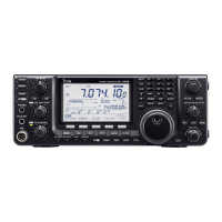
q Remove the bottom cover as shown on the previ-
ous page.
w Remove the 4 screws from the shield cover of the
RF unit, and disconnect P2 (CHASSIS) from J761
(MAIN), then lift up the shield cover.
e Remove the 8 screws from the RF unit, disconnect
J1, J121 and J151, then remove the RF unit.
r Remove the supplied internal crystal and replace
with the CR-338.
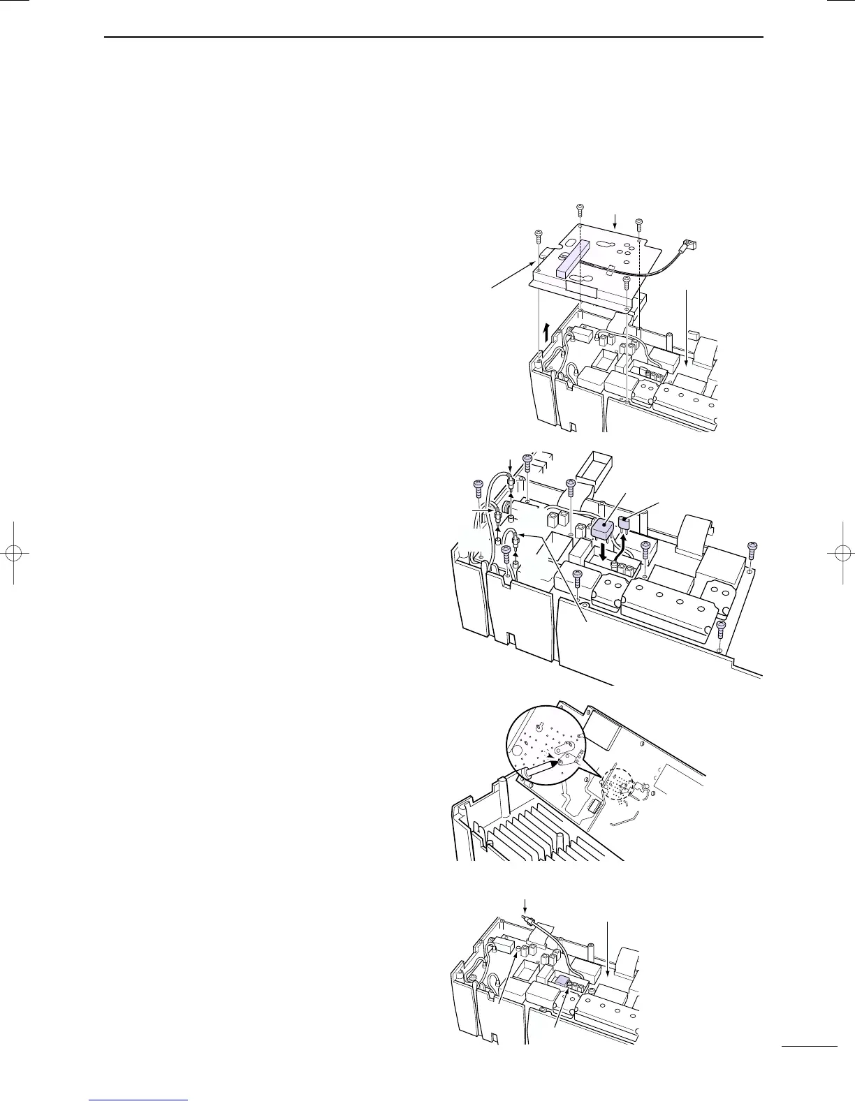
t Return the RF unit, J1, J121 and J151 to their orig-
inal positions.
y Connect a frequency counter to the J262, 2LO IN,
then adjust the reference frequency to be
64.00000 MHz with the L1901 on the RF unit.
u Return the J262, shield cover, P2 and bottom cov-
ers to their original positions.
Shield cover
RF unit
J761
(MAIN unit)
P2
(CHASSIS)
TUNER
(antenna tuner)
connector
Black belt
Blue
belt
J151
Blue
J1
Black
J121
Red
CR-338
Supplied crystal
Red belt
Connect a frequency counter, then adjust
the frequency to be 64.00000 MHz.
RF unit
J262
2LO IN
L1901
IC-7400.qxd 02.4.2 11:36 Page 90

 Loading...