9
1
PANEL DESCRIPTION
2001 NEW 2001 NEW
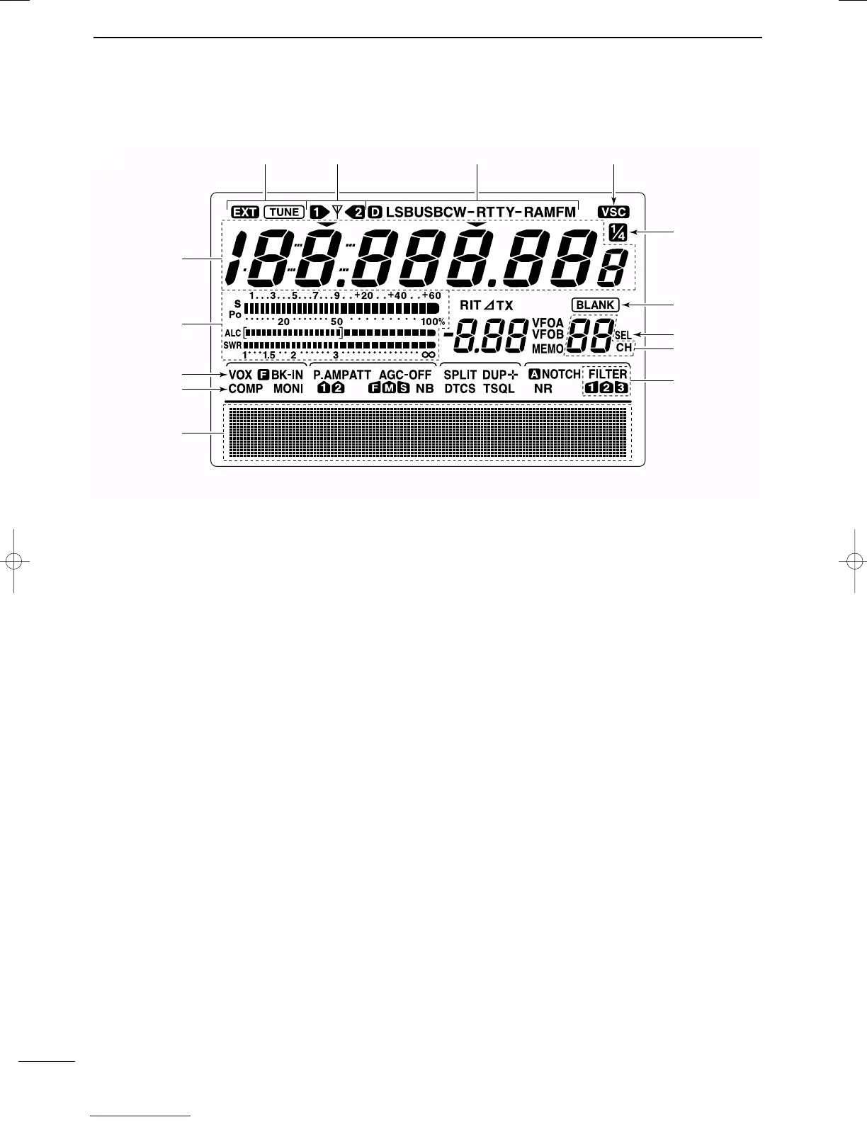
■ LCD display
q FREQUENCY READOUTS
Shows the operating frequency.
w MULTI-FUNCTION METER INDICATION
➥ Shows receiving signal strength, etc. during re-
ceive.
➥ Shows transmit output power, ALC and SWR dur-
ing transmit.
e VOX INDICATOR (p. 54)
Appears when the VOX function is activated.
r
MICROPHONE COMPRESSOR INDICATOR (p. 57)
Appears when the microphone compressor is acti-
vated.
t MULTI-FUNCTION SWITCH INDICATOR (p. 11)
Indicates the functions assigned to the multi-func-
tion switches ([F1]–[F5]).
y DSP FILTER INDICATOR (p. 49)
Shows the selected IF filter.
u MEMORY CHANNEL READOUTS (p. 61)
Shows the selected memory channel.
i SELECT MEMORY CHANNEL INDICATOR (p. 71)
Appears when the selected memory channel is set
as a select memory channel.
o BLANK MEMORY INDICATOR (p. 61)
Appears when the selected memory channel is
blank.
!0
1
⁄4 TUNING DIAL SPEED INDICATOR (p. 21)
Appears when the tuning dial speed is set so that
one rotation is equal to
1
⁄4 of the normal rotation.
!1 VOICE SQUELCH CONTROL INDICATOR (p. 53)
Appears during VSC (Voice Squelch Control) func-
tion is activated.
!2 MODE INDICATORS (p. 23)
Shows the selected operating mode.
•“D” appears when SSB data, AM data or FM data mode
is selected.
!3 ANTENNA INDICATOR (p. 74)
Indicates which antenna connector is used for
HF/50 MHz.
!4 ANTENNA TUNER INDICATORS (pgs. 75, 76)
➥ “TUNE” appears when the antenna tuner is ON;
“TUNE” appears and flashes during tuning.
➥ “EXT” appears when the optional AH-4 external
antenna tuner is connected to [ANT1].
IC-7400.qxd 02.4.2 11:35 Page 9
 Loading...