VIII
QUICK REFERENCE GUIDE
2001 NEW
d. Filters:— continued
•
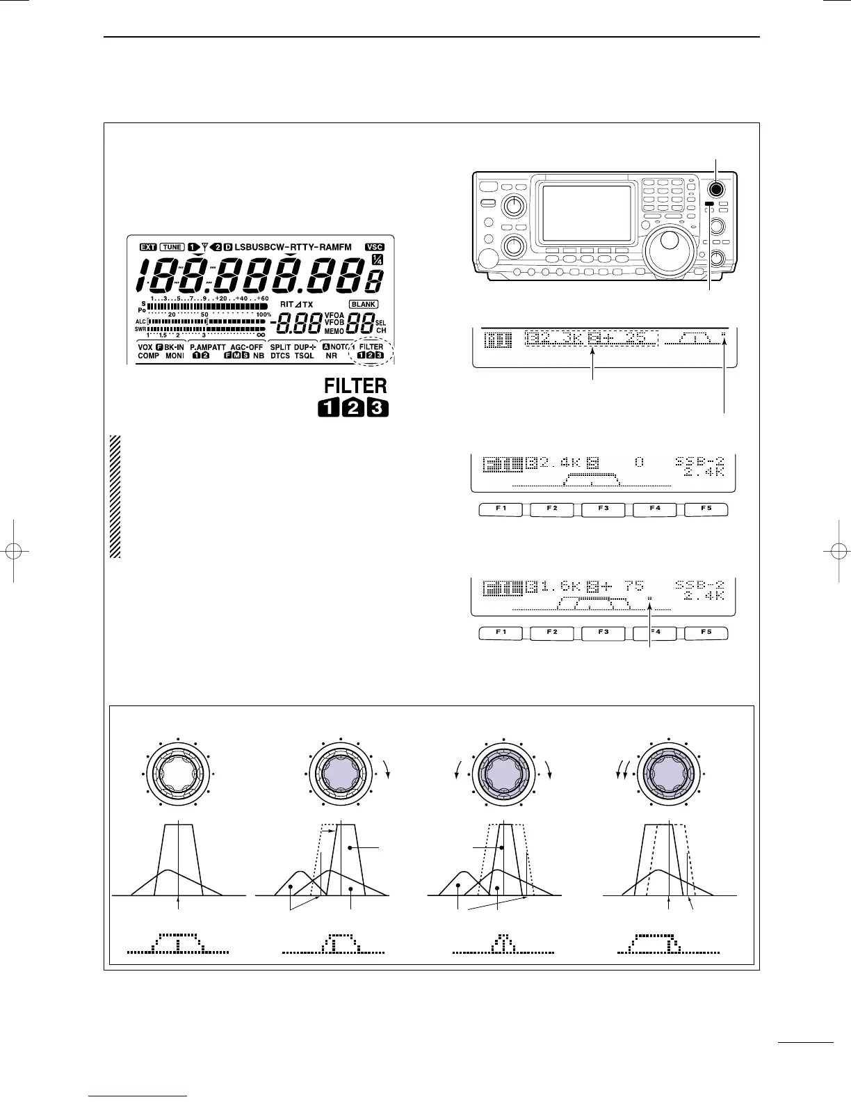
On the fly adjustment: Once the adjustments have
been made in the filter set mode, you can make on
the fly changes by using the Twin Pass Band Tuning,
Twin PBT. You will be able to see the effects of the
Twin PBT on the upper left hand side of the screen.
NOTE: The Twin PBT filters shift the two IF DSP
filters (See Diagrams below and right). This feature
allows both an IF shift as well as a narrowing of the
Pass Band. Although you can narrow the pass
band by shifting the two filters, this does not nar-
row both filters, thus the filter shape is not nar-
rowed. You may hear some signal artifacts pass
through this filter adjustment.
PBT operation example
BW
• Filter set mode indication
Shows the selected filter and passband width.
BW
• Indication while PBT setting
Appears when passband is shifted.
*By pushing [PBTC] for 1 sec., the shifted value returns
to the default setting, and the “dot” disappears.
AGC
DUP
CMP
TBW
SCP
Passband width and shifting value are
indicated while [TWIN PBT] is operated.
[TWIN PBT] control
[PBTC]
Appears when PBT is used.
One of “1,” “2” or “3” is
displayed for selected filter
number indications.
interference
inteference
interference
desired signal
desired signal
pass band
IF center frequency
Center
Passband
Passband
IF center freq.
IF shift
IC-7400.qxd 02.4.2 11:35 Page VIII
 Loading...