18
REMOTE CONTROL
Remote control (CI-V) information
D Command formats
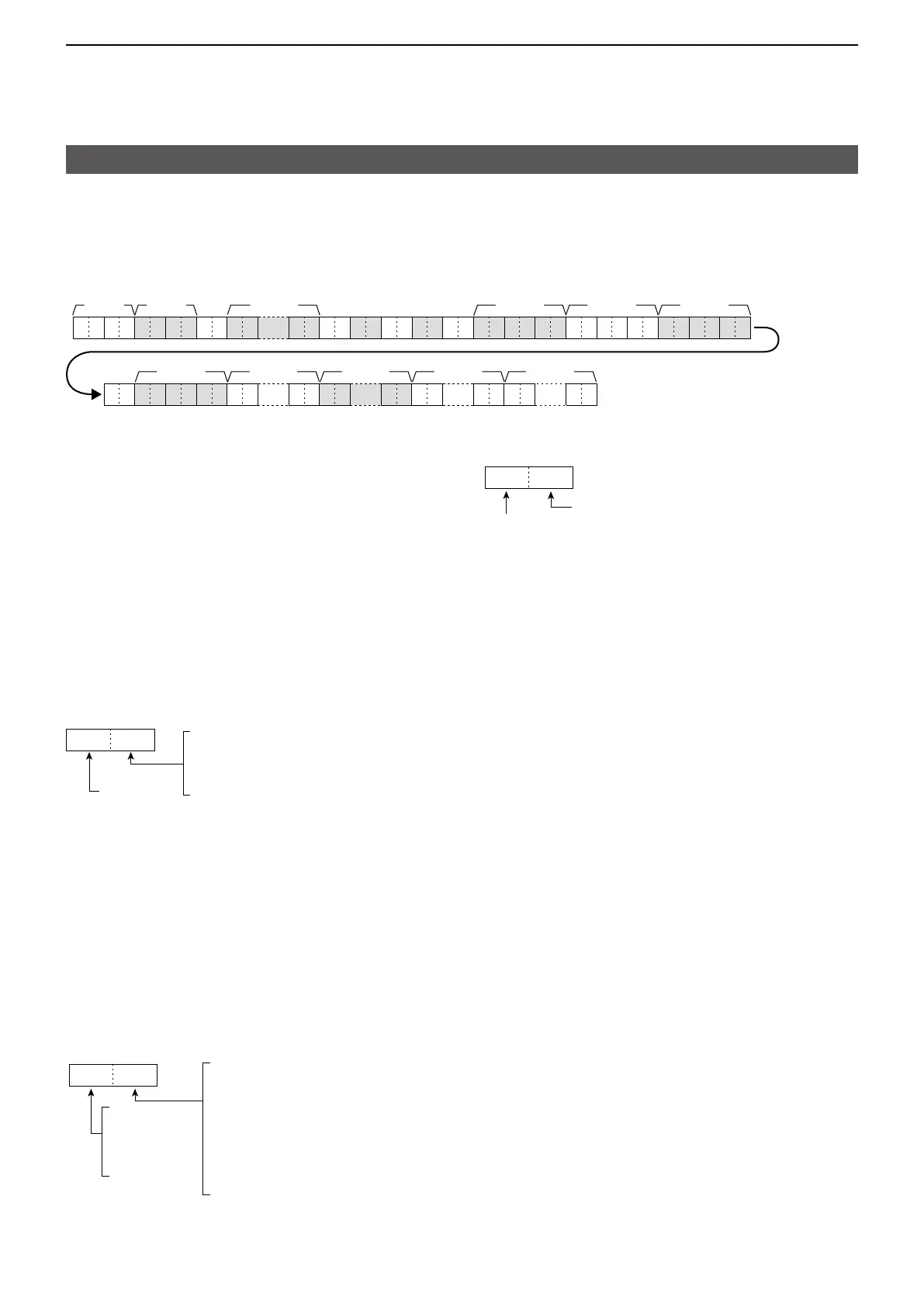
• Memory content
Command: 1A 00
0
X X X
……
X X X X X X X X X X X 0 X X X X X XX XX X X XX X
X X
X X X XX XX X X XX X
X X
……
X X
……
X X
X XX X
……
X XX X
……
X X
3
41
2 5
6
~ ~ ~ ~ ~
X X X XX X
1, 2: Memory group number
00 00 ~ 00 99: Memory channel group
01 00: Call channel group
3, 4: Memory channel numbers
• When Memory channel group is selected,
00 00 ~ 00 99: 00 ~ 99
• When Call channel group is selected,
00 00, 00 01: 144 C1, C2
00 02, 00 03: 430 C1, C2
00 04, 00 05: 1200 C1, C2
00 06, 00 07: 2400 C1, C2
00 08, 00 09: 5600 C1, C2
00 10, 00 11: 10G C1, C2
5: Split and Select memory setting
0X
5
0=OFF*
1= 1
2= 2
3= 3
Fixed
* Set 0 for Call channel�
6~: Operating frequency setting
L See “Operating frequency�” (p� 16)
, : Operating mode setting
L See “Operating mode�” (p� 16)
: Data mode setting
1 byte data (XX)
00: Data mode OFF
01: Data mode ON
: Duplex and Tone settings
X X
0=Duplex OFF
1=
Duplex−
2=Duplex+
3=RPS
0=OFF
1=TONE
2=TSQL
3=DTCS
4=DTCS(T)
5=TONE(T)/DTCS(R)
6=DTCS(T)/TSQL(R)
7=TONE(T)/TSQL(R)
L RPS can be set when DD mode is selected, and Duplex
(+, -) can be set when other than DD mode is selected�
: Digital squelch setting
X 0
0=Digital squelch function OFF
1=Digital call sign squelch function ON (DSQL)
2=Digital code squelch function ON (CSQL)
Fixed
~: Repeater tone frequency setting
~: Repeater tone frequency setting
L See “Repeater tone/tone squelch frequency setting�”
(p� 23)
~: DTCS code setting
L See “DTCS code and polarity setting�” (p� 23)
: DV Digital code squelch setting
L See “DV Digital code squelch setting�” (p� 23)
~: Duplex offset frequency setting
L p� 17)
~: UR (Destination) call sign setting
(8 characters, fixed)
~: R1 (Access repeater) call sign setting
(8 characters, fixed�)
~: R2 (Gateway/Link repeater) call sign setting
(8 characters, fixed)
L See “DV TX call signs setting�” (p� 23)
~: Memory name setting (16 characters, fixed)
L See “Codes for character entries�” (p� 19)
To clear the memory channel contents on 1A 00:
1, 2: Memory channel group (00 00 ~ 00 99)
You cannot specify group “01 00” (Call channel
group)
3, 4: Memory channel (00 00 ~ 00 99)
5: “FF,” 6 ~ : None
 Loading...