2
REMOTE CONTROL
Remote control (CI-V) information
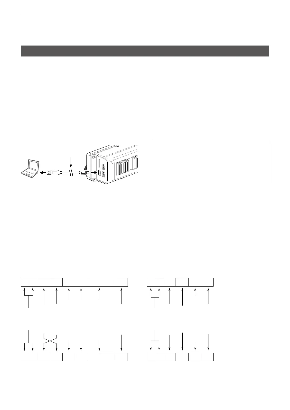
To use the USB cable between the transceiver and a
PC, you must first install a USB driver�
The latest USB driver and installation guide can be
downloaded from the Icom website�
Carefully read the guide, before installing the driver�
https://www�icomjapan�com/support/
USB cable
(User supplied)
PC
To a USB port To the [USB] port
Right side panel
D Preparing
The Icom Communications Interface V (CI-V) is used for remote control�
To control the transceiver, first set its address, data communication speed, and transceive function�
These settings are set in the Set mode (Refer to the IC-905 Basic manual)�
D About the data format
The CI-V system can be written using the following data formats� Data formats differ according to command
numbers� A data area or sub command is added for some commands�
Controller (PC) to IC-905 OK message to controller (PC)
NG message to controller (PC)IC-905 to controller (PC)
D CI-V connection
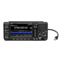
The transceiver’s operating frequency, mode, VFO and memory selection, can be remotely controlled using a PC�
The Icom Communications Interface V (CI-V) controls the transceiver�
Connect the transceiver to a PC with a USB cable (User supplied)�
L Make the connection as short as possible� The transceiver may not be recognized by the PC, depending on the
USB cable length�
L When connecting to a USB port on your PC with the USB driver installed, USB (A) and USB (B) are named as
“IC-905 Serial Port A (CI-V)” and “IC-905 Serial Port B�”
L
See the transceiver’s instruction manual for details�
FE FE AC E0 Cn Sc Data area FD
Preamble
code (fixed)
Transceiver’s
default address
Controller’s (PC’s)
default address
Command number
(see the command table)
Sub command number
(see the command table)
BCD code data for
frequency or memory
number entry
End of message
code
(fixed)
FE FE E0 AC FB FD
FE FE E0 AC FA FD
Preamble
code (fixed)
Controller’s (PC’s)
default address
Transceiver’s
default address
OK code
(fixed)
End of message
code (fixed)
NG code
(fixed)
1 2 3 4 5 6 7
FE FE E0 AC Cn Sc Data area FD
1 2 3 4 5 6 7
 Loading...