3
REMOTE CONTROL
Remote control (CI-V) information
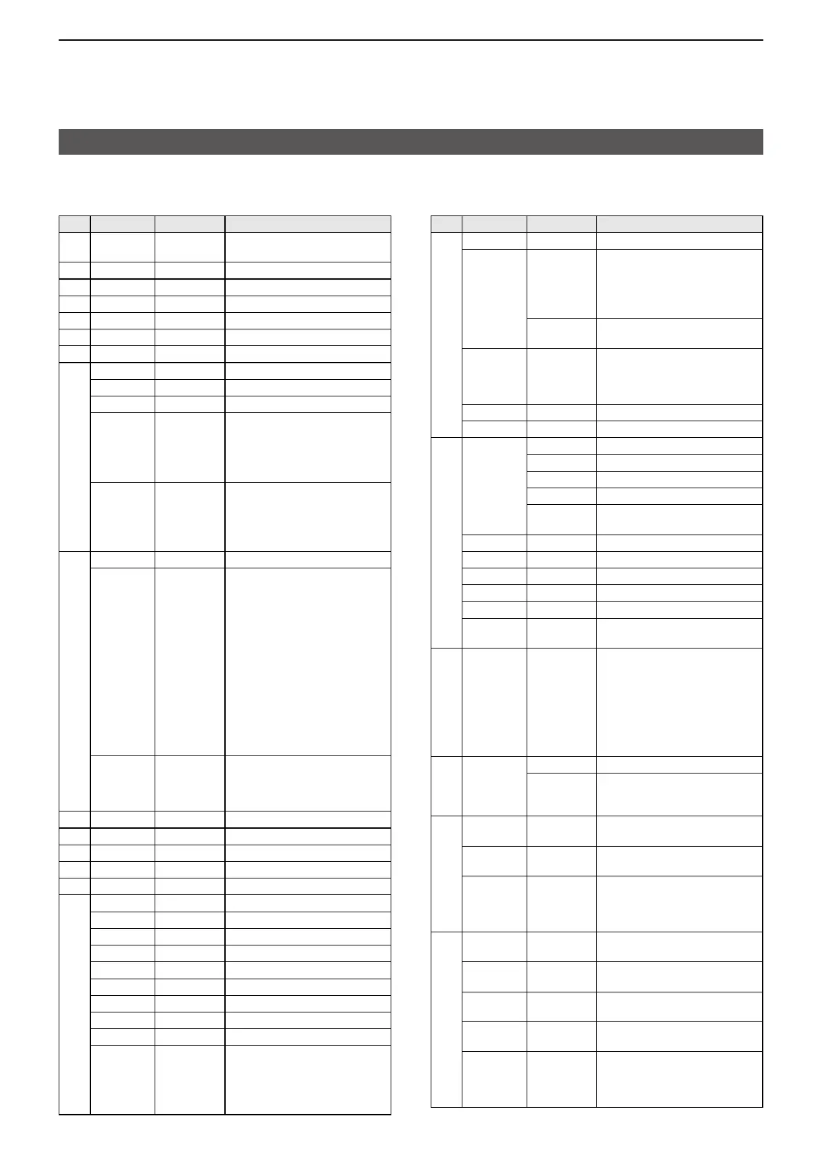
D Command table
Cmd�
Sub cmd� Data Description
00 See p� 16� Send the frequency data
(transceive)
01 See p� 16� Send the mode data (transceive)
02*
1
See p� 16� Read the band edge frequencies
03*
1
See p� 16� Read the operating frequency
04*
1
See p� 16� Read the operating mode
05*
2
See p� 16� Set the operating frequency
06*
2
See p� 16� Set the operating mode
07 Select the VFO mode
00 Select VFO A
01 Select VFO B
A0 Equalize VFO A and VFO B
L When the split frequency
operation is OFF in the Memory
mode or the Call channel mode,
“FA” (NG) is returned�
B0 Exchange VFO A and VFO B�
L When the split frequency
operation is OFF in the Memory
mode or the Call channel mode,
“FA” (NG) is returned�
08*
2
Select the Memory mode
00 00 ~ 00 99 Select the Memory channel
( Memory channel: 00 00 ~ 00 99
Call channel: 00 00 (144C1),
00 01 (144C2),
00 02 (430C1),
00 03 (430C2),
00 04 (1200C1),
00 05 (1200C2),
00 06 (2400C1),
00 07 (2400C2),
00 08 (5600C1),
00 09 (5600C2),
00 10 (10GC1),
00 11 (10GC2)
A0 00 00 ~ 01 00 Select the Memory group
( Memory channel group:
00 00 ~ 00 99
Call channel group: 01 00)
09 Memory write
0A Memory copy to VFO
0B Memory clear
0C*
1
See p� 17� Read frequency offset
0D*
2
See p� 17� Send frequency offset
0E 00 Cancel the scan
01 Start a Programmed/memory scan
02 Start a Programmed scan
03
Start a ∂F scan
12 Start a Fine programmed scan
13
Start a Fine ∂F scan
22 Start a Memory scan
23 Start a Select memory scan
24 Start a Mode Select scan
Ax*
2
(x=1 ~ 7)
Select ∂F scan span
( x=1 (±5kHz), x=2 (±10kHz),
x=3 (±20kHz), x=4 (±50kHz),
x=5 (±100kHz), x=6 (±500kHz),
x=7 (±1MHz))
Cmd�
Sub cmd� Data Description
0E B0*
2
Clear the Select channel setting
B1*
2
Set as select channel
L The previously set number by
CI-V is set after turning power
ON, or “1” is selected if no
selection is performed�
01 ~ 03
Set the channel as a Select channel
(01=SEL1, 02=SEL2, 03=SEL3)
B2*
2
00 ~ 03 Set the Select memory scan
channel
( 00=ALL, 01=SEL1, 02=SEL2,
03=SEL3)
D0*
2
Set Scan resume OFF
D3*
2
Set Scan resume ON (Close&Delay)
0F 00*
1
Read Split OFF setting
01*
1
Read Split ON setting
11*
1
Read DUP– operation
12*
1
Read DUP+ operation
13*
1
Read DD Repeater Simplex mode
(RPS)
00*
2
Set Split function OFF
01*
2
Set Split function ON
10*
2
Set the simplex operation
11*
2
Set DUP– operation
12*
2
Set DUP+ operation
13*
2
Set DD Repeater Simplex mode
(RPS)
10* 00 ~ 12 Send/read the tuning step
( 00=OFF (10Hz or 1Hz)
01=100Hz, 02=500Hz,
03=1kHz, 04=5kHz,
05=6�25kHz, 06=10kHz,
07=12�5kHz, 08=20kHz,
09=25kHz, 10=50kHz,
11=100kHz, 12=250kHz)
11* 00 Send/read attenuator OFF setting
10
Send/read 10 dB attenuator setting
L You can set in the 144/430/1200
MHz bands�
13 00
Speech all data by voice synthesizer
(S meter level, frequency, and mode)
01
Speech the operating frequency and
S meter level by voice synthesizer
02 Speech the operating mode by
voice synthesizer
L The mode is announced after
the ongoing speech�
14* 01 00 00 ~ 02 55 Send/read the AF level
(00 00=Minimum ~ 02 55=Maximum)
02 00 00 ~ 02 55 Send/read the RF gain level
(00 00=Minimum ~ 02 55=Maximum)
03 00 00 ~ 02 55
Send/read the squelch level
(00 00=Minimum ~ 02 55=Maximum)
06 00 00 ~ 02 55
Send/read the NR level
(00 00=0% ~ 02 55=100%)
07 00 00 ~ 02 55 Send/read [TWIN PBT] (PBT1)
position
( 00 00=max� Counter Clockwise ~
01 28=center ~ 02 55=max� Clockwise)
 Loading...