19
REMOTE CONTROL
Remote control (CI-V) information
D Command formats
• Codes for character entries
Command: 1A 00,
1A 05 01 79,
02 71, 02 74 ~ 02 77,
02 80 ~ 02 83,
02 91, 02 93, 02 94,
03 05, 03 08, 03 20, 03 28
- Character codes— Letters and Numbers
Character ASCII code
A ~ Z 41 ~ 5A
0 ~ 9 30 ~ 39
Character ASCII code
a ~ z 61 ~ 7A
- Character codes— Symbols
Character ASCII code
! 21
$ 24
& 26
? 3F
’ 27
^ 5E
2D
/ 2F
, 2C
; 3B
< 3C
( 28
[ 5B
{ 7B
| 7C
7E
Character ASCII code
# 23
% 25
\ 5C
” 22
` 60
+ 2B
* 2A
� 2E
: 3A
= 3D
> 3E
) 29
] 5D
} 7D
_ 5F
@ 40
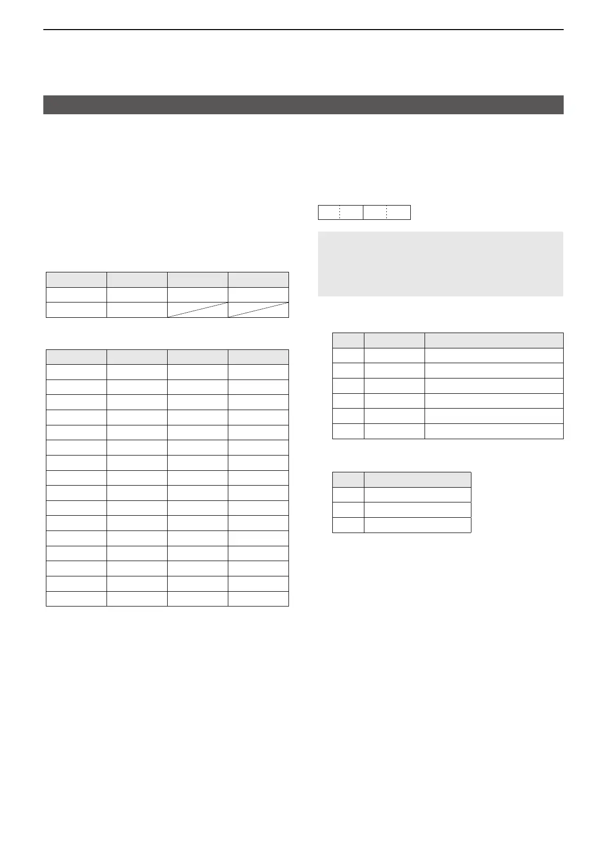
• Band stacking register
Command: 1A 01
1
XX X X
2
NOTE: When sending the contents, the codes, such
as operating frequency and operating mode*, should
be added after the frequency band code and the
register code, as shown below�
* See 6 ~ on “Memory content�” (p� 18)
1: Frequency band codes
Code Freq� band Frequency range (unit: MHz)
01 144 144�000000 ~ 148�000000
02 430 430�000000 ~ 450�000000
03 1200 1240�000000 ~ 1300�000000
04 2400 2300�000000 ~ 2450�000000
05 5600 5650�000000 ~ 5925�000000
06 10G 10000�000000 ~ 10500�000000
2: Register codes
Code Registered number
01 1 (Display on left side)
02 2 (Display in center)
03 3 (Display on Right side)
To read the contents, the register code should be
added after the frequency band code, as shown
below�
Example: When reading the frequency displayed in
the center of the display in the UHF band,
use code “02 02�”
 Loading...