44
7
INSTALLATION AND CONNECTIONS
New2001 New2001
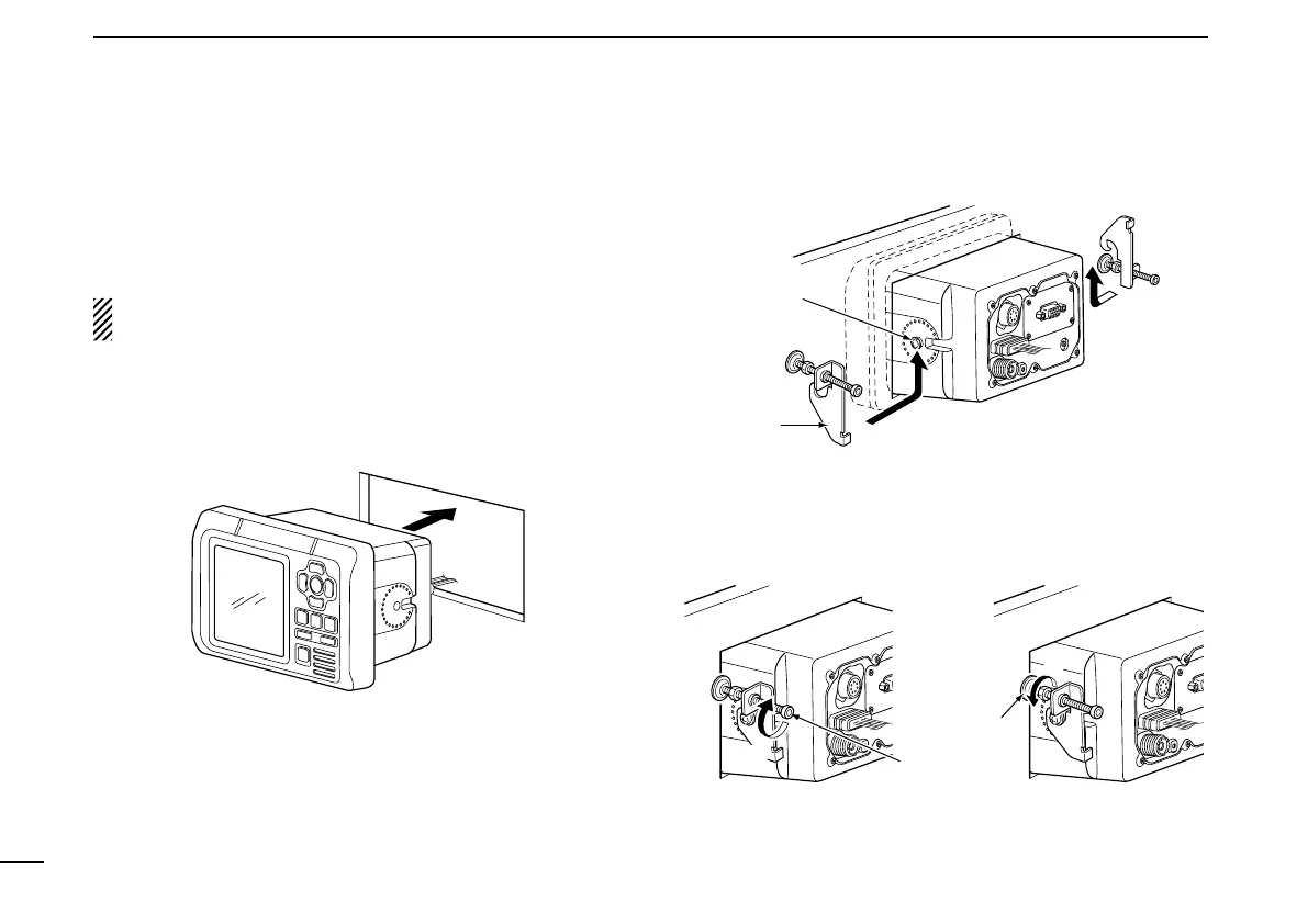
■ MB-75 installation
An optional MB-75 f l u s h m o u n t k i t is available for mount-
ing the transponder to a at surface, such as an instrument
panel.
KEEP the transponder at least 1 m (3.3 ft) away from your
vessel’s magnetic navigation compass.
q Using the template on the page 49, carefully cut a hole into
the instrument panel (or wherever you plan to mount the
transponder).
w Slide the transponder through the hole.
e Attach the 2 supplied bolts (M5 × 8 mm) on either side of
the transponder.
r Attach the clamps on either side of the transponder.
• Make sure that the clamps align parallel to the transponder’s
body.
t Tighten the end bolts on the clamps (rotate clockwise) so
that the clamps press firmly against the inside of the in-
strument control panel.
y Tighten the locking nuts (rotate counterclockwise) so that
the transponder is securely mounted in position.
u Connect the antenna, power cable, GPS receiver and
OPC-2014, then return the instrument control panel to its
original place.
 Loading...