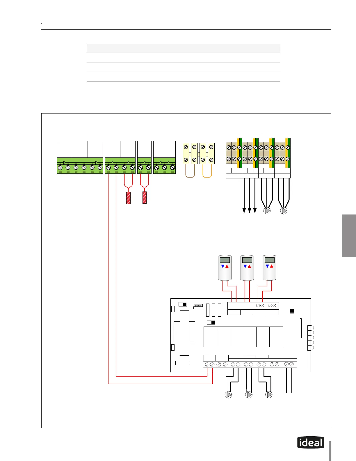
FOUR ZONE SWITCHING RELAY
WITH OPTIONAL PRIORITY
MODE
RESET NORMAL
SLAVE
MASTER
FUSE 1 AMP
ON
OFF
ZONE 4
PRIORITY
PLUG IN CARDS
1 2 3 4
EXPANSION
120 VAC
INPUT
(H & N)
Low Voltage Terminals
Outdoor Sensor
DHW Sensor
CH2
Thermostat
6 5
System
Sensor
4 3
Modulation
Signal
-+
2 1
CH2
Thermosta
t
CH1
Thermostat
4 3
Outdoor
Sensor
2 1
DHW
Sensor or
Aquastat
2 1
Modbus
+ G -
3 2 1
X7X4
X6X5
External Limit
Terminals
Manual Auto
Zone 2
Thermostat
Zone 1
Thermostat
DHWCH
120V/15A
Service
Zone 3
Thermostat
6868
68
ZONE4ZONE3ZONE2ZONE1
Zone 2
Thermostat
Zone 1
Thermostat
Zone 3
Thermostat
INPUT
POWER
120 VOLT CIRCULATORS
ZONE4
ZONE3
ZONE2ZONE1
ZRZC
X X
END
SWITCH
Line Voltage Terminals
N G L N G L N G L N G L
FLAME
POWER SUPPLY
CH PUMP
DHW PUMP
Fig. 19 - Multiple Zones - Panel Wiring with Circulators
31
TITLE
CHAPTER 5
CHAPTER 5 - EXALT COMBI UNITS - DOMESTIC PIPING
Outdoor Sensor
DHW Sensor
internal to boiler
Low Voltage Terminals
Line Voltage Terminals
External Limit
Terminals
AutoManual
EXALT COMBI PRESET PUMP CONFIGURATION
Heat Call Flame CH Pump DHW Pump
CH1 ON ON OFF
CH2 ON ON OFF
DHW OFF ON ON
Note. EXALT Combi is pre-congured for this installation
 Loading...