12
Installation and Servicing
Section 1 - General
a. The method of lling, relling, topping up or ushing sealed
primary hot water circuits from the mains via a temporary
hose connection is only allowed if acceptable to the local
water authority.
b. Antifreeze uid, corrosion and scale inhibitor uids suitable
for use with boilers having aluminium heat exchangers may
be used in the central heating system.
General
1. The installation must comply with all relevant national and
local regulations.
2. Design the system for ow temperatures up to 80
o
C.
3. The system components must be suitable for an operating
pressure of 3 bar and a maximum temperature of 110°C.
The following components are incorporated within the
appliance:
a. Circulating pump.
b. PRV, with a non-adjustable preset lift pressure of
3 bar.
c. Pressure gauge, covering a range of 0 to 4 bar.
d. An 8 litre expansion vessel, with an initial charge
pressure of 0.75 bar.
4. Makeup Water. One of the following provisions must be
made for replacing system water loss:
a. Manually lled vessel
The vessel must:
Have a visible water level
Be mounted at least 150 mm above the system’s
highest point
Connect through a non-return valve to the system
Be at least 150 mm below the makeup vessel on the
return side of the radiators
b. System prepressurisation.
The eciency of the expansion vessel will be
reduced in a pressurised system; a larger vessel or
smaller system volume may be necessary.
If the vessel’s capacity is not sucient, an additional
vessel must be installed on the return to the boiler.
If the system is not pressurised, the cold water
capacity must not exceed 143 litres.
Guidance on vessel sizing is given in table above.
1.15 SYSTEM REQUIREMENTS - CENTRAL HEATING
PRV setting bar 3.0
Vessel charge pressure bar 0.5 to 0.75
System pre-charge pressure bar None 1.0
System volume Expansion vessel
(litres) volume (litres)
25 1.6 1.8
50 3.1 3.7
75 4.7 5.5
100 6.3 7.4
125 7.8 9.2
150 9.4 11.0
175 10.9 12.9
190 11.9 14.0
200 12.5 14.7
250 15.6 18.4
300 18.8 22.1
For other system volumes
multiply by the factor across 0.063 0.074
5. Filling
The system may be lled by the following method:
Where the mains pressure is excessive a pressure
reducing valve must be used to facilitate lling.
a. Thoroughly ush out the whole system with cold
water.
b. Fill and vent the system until the pressure gauge
registers 1 bar and examine for leaks
c. Check that a 15 mm diameter pipe is correctly
located and secured (using the clip supplied)
d. Check the operation of the PRV by raising the water
pressure until the valve lifts. This should occur within
0.3 bar of the preset lift pressure.
e. Check no escape of water occurs except at the
discharge point
f. Release water from the system until the
minimum system design pressure is reached;
1.0 bar if the system is to be pre-pressurised.
Model 15 18 24 30
Max CH uutput kW 15 18 24.2 30.3
Water ow rate l/min 10.7 13 17.2 21.5
(gal/min) (2.4) (2.8) (3.8) (4.7)
Temp dierential
o
C 20 20 20 20
Head available m.w.g. 5 4.5 3.3 1.9
for system (ft.w.g.) (16.2) (14.7) (10.8) (6.2)
With Ideal System m.w.g.
Filter & Valves (ft.w.g.)
4.9
16
4.3
14.1
3.0
9.8
1.5
4.9
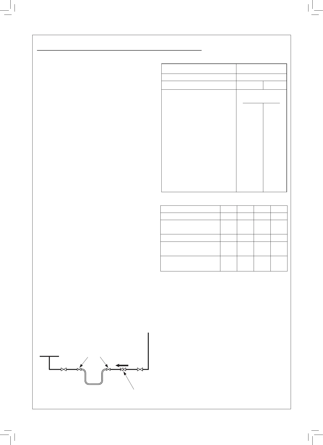
CH Return
Ecl 6053
Hose unions
Mains
water supply
Temporary hose
(disconnect after filling)
Additional
stop valve
Double check valve
assembly
(
note direction of flow
)
Table 3 Vessel Sizing
Table 4
 Loading...


