24
Installation and Servicing
Section 2 - Installation
INSTALLATION
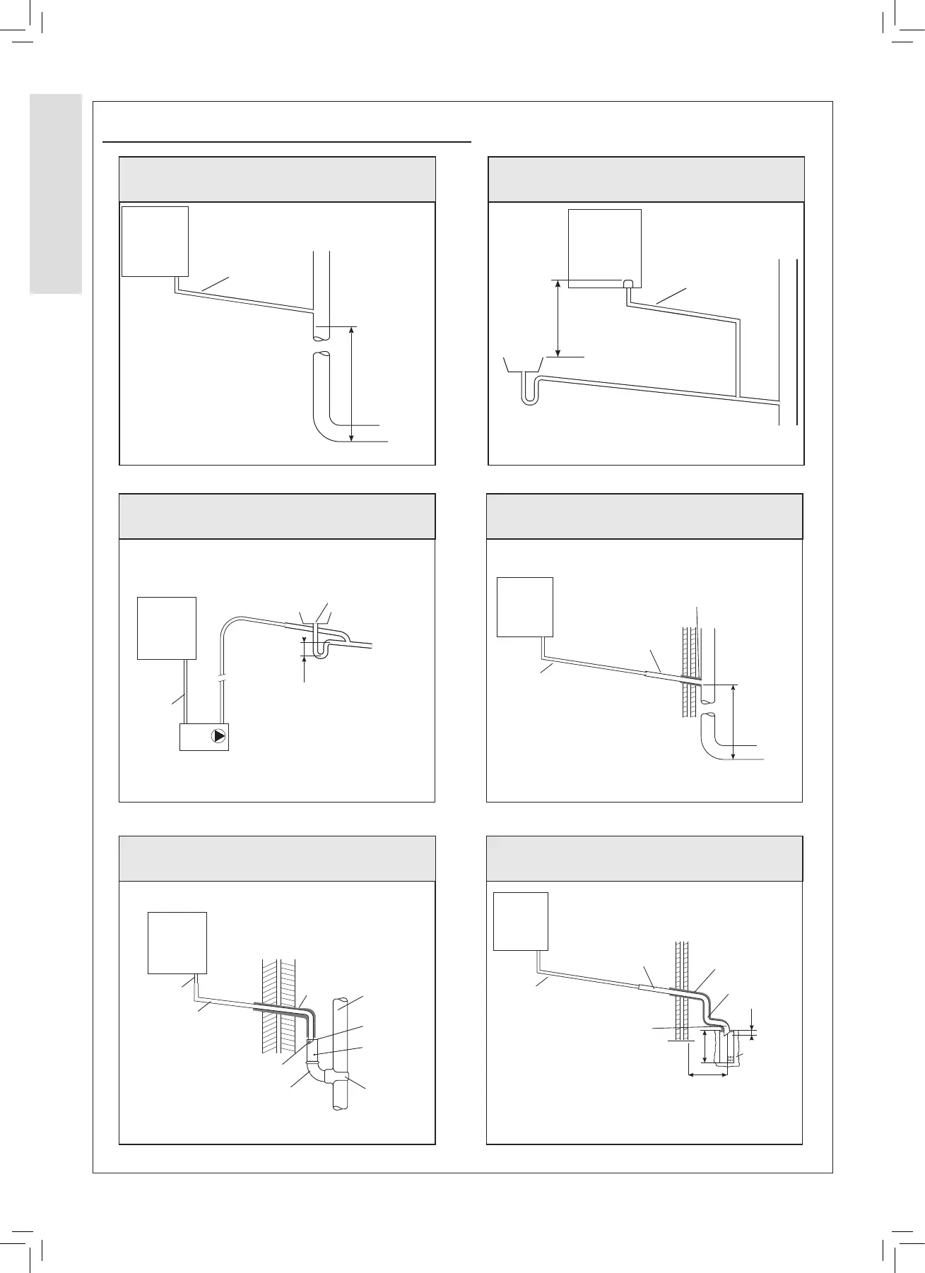
Boiler
with 75 mm
sealed
condensate
trap
Min Ø 19 mm
Internal pipe
Minimum
connection
height up to 3
storeys
Soil & vent stack
≥ 450 mm
Sink/basin/
bath or
shower
Boiler
with 75 mm
sealed
condensate
trap
Min Ø 19 mm
Internal pipe
Internal soil & vent stack
≥ 100 mm
Figure 1 - Connection of Condensate Drainage Pipe to
Internal Soil & Vent Stack
Figure 2 - Connection of a Condensate Drainage Pipe
Downstream of a Sink, Basin, Bath or Shower Water Trap to
Internal Soil Vent Stack
2.16 CONDENSATE DRAIN - CONTINUED
Visible air break
Condensate pump
(Install in accordance with manufacturers instructions)
Min Ø 19 mm
Internal pipe
Boiler
with 75 mm
sealed
condensate
trap
75 mm
Min Ø 19 mm
Internal pipe
Min Ø 30 mm
Internal pipe
Air gap
External air
break
Combined foul/
rain water drain
Terminated
and cut at 45º
43 mm 90º
male/ female
bend
Water/
weather proof
insulation
68 mm Ø PVCU
Strap on fitting
Boiler
with 75 mm
sealed
condensate
trap
Boiler
with 75 mm
sealed
condensate
trap
Min Ø 19 mm
Internal pipe
Min Ø 30 mm
Internal pipe
Water/Weather
proof insulation
Max 3 m external
pipework
Limestone
chippings
≥ 500
≥ 300
≥ 25
2 rows of three Ø12 mm holes
25 mm centres, 50 mm from
the bottom of the tube, facing
away from the house
Terminated
and cut at 45º
Minimum
connection
height up to 3
storeys
Soil & vent stack
≥ 450 mm
Boiler
with 75 mm
sealed
condensate
trap
Min Ø 19 mm
Internal pipe
Min Ø 30 mm
Internal pipe
Water/weather
proof insulation
Figure 3 - Connection of a Condensate Pump Typical
Method (see manufacturer’s detailed instructions)
Figure 4 - Connection of Condensate Drainage Pipe to
External Soil & Vent Stack
Figure 5 - Connection of a Condensate Drainage Pipe to an
External Rainwater Downpipe (only combined foul/rainwater
drain)
Figure 6 - Connection of a Condensate Drainage Pipe to an
External Purpose Made Soakaway.
 Loading...


