25
Installation and Servicing
Section 2 - Installation
INSTALLATION
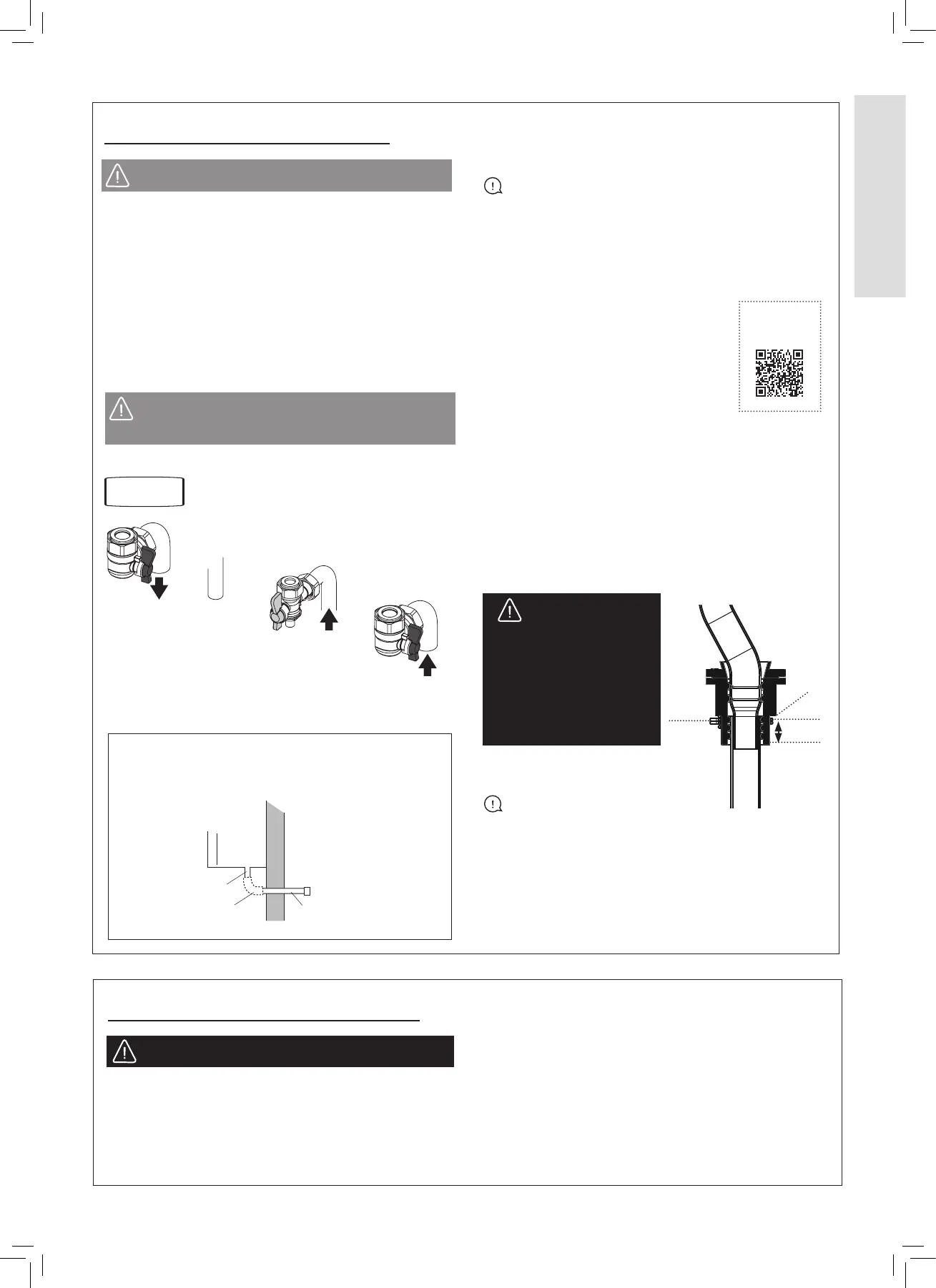
PRV
Drain Connection
15 mm Fitting
(not supplied)
PRV
Drain Pipe (supplied)
A purpose made PRV drain pipe is provided with the boiler
to allow safe discharge through a wall to the outside of the
building. This is particularly relevant to ‘high rise’ installations
but can be used for all installations.
PRV DRAIN
The PRV connection, located at the bottom left-hand side of
the boiler, comprises an open ended grommet.
IMPORTANT
The grommet is designed for 15 mm Ø copper pipe.
If possible, preassemble and solder the pipework before
Installing.
If this is not possible the soldering must be more than
100 mm away from the grommet. Make sure the grommet
is not damaged by the heat.
Install the condensate pipe as follows:
1. Make sure that the 15 mm Ø copper
pipe is cut perpendicular to the pipe.
2. Make sure that the pipe is not
damaged, and clean and free from burs.
3. Using pliers put the clip over the
grommet. Continue to hold the clip open.
Note. Do not release the clip until step 5 (see below).
4. Push the copper pipe into the grommet (minimum of
15 mm). Make sure that the pipe is parallel with the
grommet.
5. Below the stop mark on the grommet open the pliers to
release the clip.
6. Make sure that the clip and pipe are attached correctly.
7. Make sure that the PRV discharge pipe is correctly
attached. Make sure that the angle of the pipe run is
sucient to remove discharged water.
.
FILLING
IMPORTANT - when lling:
A. Ensure the dust cap on air vent located at the rear of the
pump chamber is slightly unscrewed.
B. When lling, there may be a slight water leak from
the air vent therefore electrical connections should be
protected.
1. Ensure that the CH isolating handles are open.
2. Fill and vent the system. Check for water soundness.
Isolation handles are shown in the open position.
Yellow
Handle
Black
Handle
Black
Handle
CH Flow
Gas
Supply
CH Return
PRV
Outlet
Remove all boss blanking plugs before connecting the
hardware.
Fit each union with the bre seals provided.
WATER CONNECTIONS CH
1. Connect the CH ow service valve (black handle) and
copper tail provided in the hardware pack to the threaded
boss connection provided at the lower rear of the boiler.
2.
Connect the CH return. valve (black handle) and copper tail.
GAS CONNECTION
For details of the position of the gas connection:
Refer to Gas Supply
1.9
CAUTION: The gas service cock is sealed with a
non-metallic blue bre washer, which must not be
overheated when making capillary connections.
Stop
point
Clip
15 mm
SCAN
for video
WARNING:Make
sure that the water or
steam (from the boiler)
is discharged safely.
Hot water or steam is
dangerous and can cause
serious injury, and damage
to electrical systems.
2.17 CONNECTIONS & FILLING
CAUTION: Heating the isolation valves may damage
the bre seals
2.18 ELECTRICAL CONNECTIONS
Wiring should be 3 core PVC insulated cable, not less than
0.75 mm
2
(24 x 0.2 mm), and to BS 6500 Table 16.
Connection must be made in a way that allows complete
isolation of the electrical supply. The means of isolation
must be accessible to the user after installation.
A mains supply of 230 V ~ 50 Hz is required.
3 A fuse required. All external controls and wiring must be
suitable for mains voltage.
Wiring external to the boiler must follow current I.E.E
(BS7671) wiring regulations and local regulations.
WARNING: This appliance must be earthed
 Loading...


