16
Installation and Servicing
Section 2 - Installation
INSTALLATION
IMPORTANT:
Ensure the wall where the boiler will be is
at.
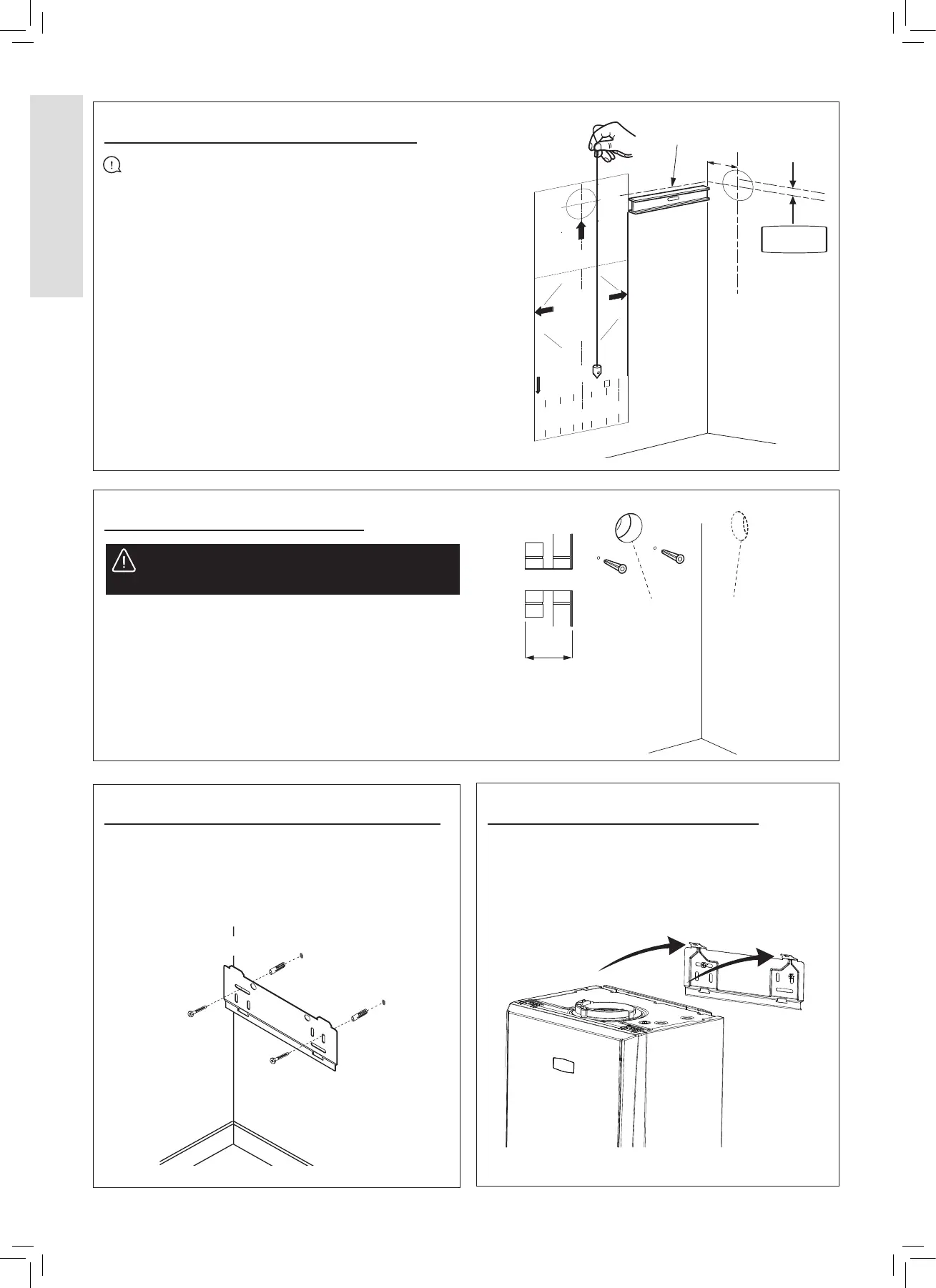
The wall mounting template is located on the internal
protective packaging. The template shows the position
of the xing and rear ue centre holes for a standard
installation.
1. Secure the template into the required position. Ensure it
is square by hanging a plumbline.
2. If tting a side ue, extend the ue centreline onto the
side by 155 mm on a standard wall x or 200 mm if
using a stand-o bracket.
3. Mark the following on to the wall:
a The selected group of wall mounting screw holes.
b. The centre position of the ue duct. Marking both the
centre and the circumference of the ue duct.
4. Remove the template plate from the wall.
2.3 WALL MOUNTING TEMPLATE
2.4 PREPARING THE WALL
1. Check all of the hole positions before drilling.
2. Cut the ue hole with a 127 mm core boring tool, ensure
the hole is square to the wall.
3. Drill the 2 mounting holes with a 7.5 mm / 8 mm masonry
drill and insert the plastic plugs provided.
4. Locate 2 No.14 x 50 mm screws in the wall mounting plate
(one at each side, in any of the 3 holes provided at each
side) and screw home. Ensure mounting bracket is level.
2.5 FITTING THE WALL MOUNTING PLATE
2.6 MOUNTING THE BOILER
Screw the wall mounting plate to the wall using 2 wall plugs
tted previously with the 2 screws provided.
Choose one of the 2 sets of slots in left and right bank.
Ensure that at least one of the screws is tted into a top slot
and the mounting bracket is level.
“A”
Extended centre line
155
(200)
X
Section
through wall
Side flue only
127 mm diameter hole
Rear flue only
127 mm diameter hole
Refer to Section
2.7
1. Lift the boiler onto the wall mounting plate and locate it
over the 2 tabs.
WARNING: Ensure that, during the cutting
operation, masonry falling outside of the building does
not cause damage or personal injury.
 Loading...


