WARNING: The
appliance MUST be
efficiently earthed.
A mains supply of
240 V ~ 50 Hz is
required.
All external controls and wiring
MUST be suitable for mains
voltage. Wiring should be in
3-core PVC insulating cable
NOT LESS than 0.75 mm
2
(24 x 0.2 mm) to BS.6500, Table 16.
Wiring external to the boiler MUST be in accordance with current
l.E.E. Wiring Regulations and local regulations.
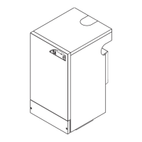
The supply connection may be made via a removable plug to a
shuttered socket/outlet, preferably adjacent to the boiler, and,
should such a plug be used for connection to the mains, it MUST
be of the 3-pin type, wired as shown, fused at 3A and comply with
the requirements of BS.1363. Alternatively, a fused double-pole
switch, having a 3 mm contact separation in both poles, serving
only the boiler and its external controls, may be used.
Note: If the optional Programmer Kit is to be fitted, refer to the
instructions provided with the kit, ignore this Frame and go to
Frame 16.
The internal wiring of the control box is shown in Frame 17.
A wiring diagram is also contained in the Lighting Instructions
(inside the control pod door).
11
INSTALLATION
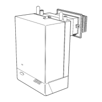
14 GAS CONNECTION
A MINIMUM gas pressure of 20 mbar (8 in.w.g.) MUST be
available at the boiler inlet.
The main gas cock is on the left hand side of the gas control
valve, as shown.
To facilitate connection it is recommended that the gas cock
is not removed from the gas control valve.
SERVICE CONNECTIONS - WIRING DIAGRAMS
Also refer to 'Gas supply' - page 3.
16 EXTERNAL CONTROLS
The wiring diagrams illustrated in Frames 18 - 21 cover the
systems most likely to be fitted to this appliance.
For wiring external controls to the Ideal Classic RS boiler,
reference should be made to the system wiring diagrams
supplied by the relevant manufacturer, in conjunction with the
wiring diagrams shown in Frames 17 - 21.
Difficulty in wiring should not arise, providing the following
directions are observed:
1. Controls that switch the system ON and OFF, e.g. a time
switch MUST be wired in series in the live mains lead to
the boiler.
2. Controls that over-ride an ON/OFF control, e.g. a frost
thermostat, MUST be wired into the mains lead, in parallel,
with the control(s) to be over-ridden - refer to Frame 21.
3. Controls that switch the circulation pump only ON and
OFF, e.g. a room thermostat, MUST be wired in series with
the pump in the live pump lead.
4. If a proprietary system is used, follow the instructions
supplied by the manufacturer.
5. SYSTEM DESIGNS FEATURING CONTROLS OR
WIRING ARRANGEMENTS WHICH ALLOW THE BOILER
TO FIRE WHEN THERE IS NO PUMPED OR GRAVITY
CIRCULATION TAKING PLACE SHOULD NOT BE
FITTED.
Advice on required modifications to the wiring may be obtained
from the component manufacturers.
Notes 1. Connections between a frost thermostat and the
time control should be made without disturbing
other wiring.
2. A frost thermostat should be sited in a cool
place in the house, but where it can sense heat
from the system.
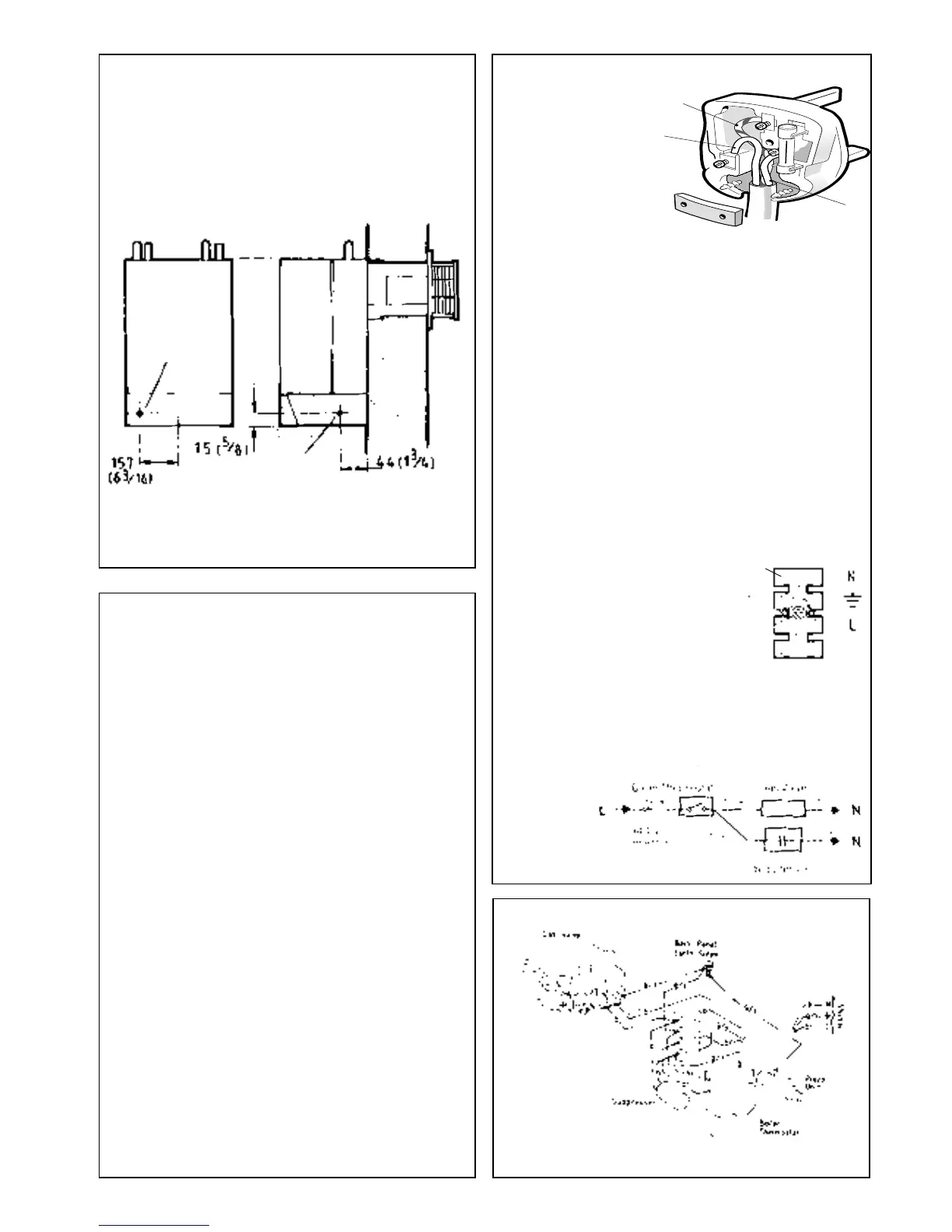
Terminal strip
Alignment
pegs
Terminal
fixing
screw
17 PICTORIAL WIRING
Note: In order to connect the
incoming mains wires, first
remove the control box cover,
then remove the terminal fixing
screw and lift the terminal strip
clear of the control box (refer to
Fr. 23 'Servicing').
Ensure that the earth lead is longer than the live and neutral so
that if the cable slips in its anchorage the current carrying
conductors become taut before the earth conductor and that the
cable is routed through the strain relief clamp. Ensure all cables
are secure and that no basic insulation is accessible outside of the
control box. (Refer diagram in Frame 23, 'Servicing').
15 ELECTRICAL CONNECTIONS
DETAIL OF CONTROL BOX TERMINALS
FLOW WIRING
DIAGRAM
LEGEND
br brown g/y green/yellow b blue
Gas
inlet
Gas inlet
 Loading...