INSTALLATION
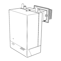
18 MID POSITION VALVE
Pumped only
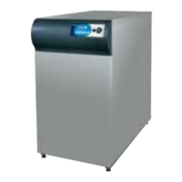
19 TWO SPRING CLOSED VALVES
Pumped only
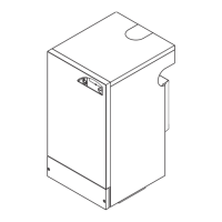
20 HONEYWELL 'C' PLAN
Notes:
1. Some earth wires are omitted for clarity. Ensure proper earth
continuity when wiring.
2. Numbering of terminals on thermostats is specific to the
manufacturer.
3. This is a fully controlled system - set the boiler thermostat to
maximum.
4. Switchmaster 'Midi' is similar in operation but the wiring differs
slightly; see manufacturer's literature.
Gravity HW & Pumped CH
Mains
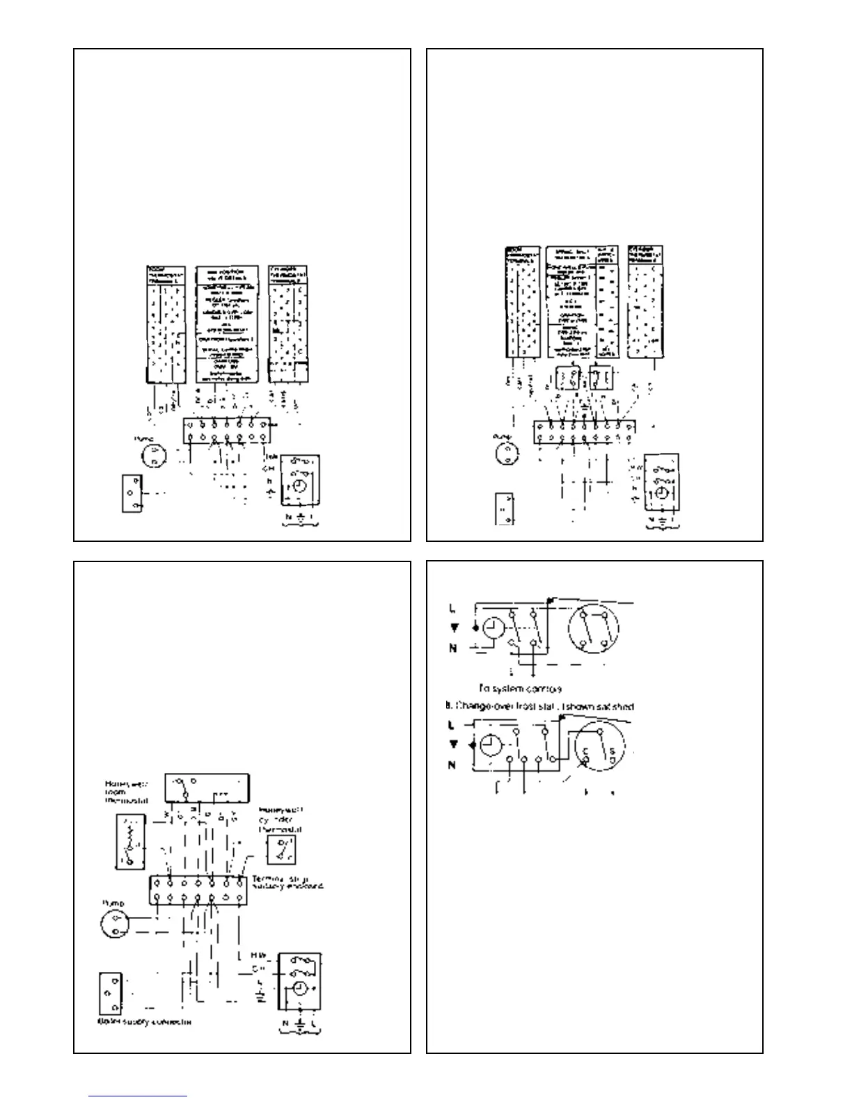
21 FROST PROTECTION
A. Double pole frost 'stat, e.g. SOPAC TA37.04
Typical programmer
using change-over
contacts
Typical Programmer
Off
OffOnOn
CHHW
To system controls
Boiler supply connector
12
Typical programmer
CH may be
selected
independently of
HW
V4043H 1049 in HW circuit
Notes:
1. Some earth wires are omitted for clarity. Ensure proper
earth continuity when wiring
2. Numbering of terminals on thermostats is specific to the
manufacturer.
LEGEND
w - white bk - black br - brown
or - orange b - blue gy - grey
g - green r - red y - yellow
Central heating systems fitted wholly inside the house do not normally
require frost protection as the house acts as a 'storage heater' and can
normally be left at least 24 hrs. without frost damage. However, if parts of
the pipework run outside the house or if the boiler will be left off for more
than a day or so, then a frost 'stat should be wired into the system. This is
usually done at the programmer, in which case the programme selector
switches are set to 'Off' and all other controls MUST be left in the running
position. The frost 'stat should be sited in a cold place but where it can
sense heat from the system. Wiring should be as shown, with minimal
disturbance to other wiring of the programmer. Designation of the terminals
will vary, but the programmer and thermostat manufacturer's leaflets will
give full details. Diagram A shows a double pole frost 'stat, which should
suffice for all systems which do not use the 'OFF' terminals of the
programmer. Diagram B shows a 'change-over' frost 'stat, which will cover
most systems which do use 'CH OFF.' If, however, on such a system the
HW pipework is in an isolated part of the house, a second frost 'stat may
be used to protect it. If in doubt, ask your installer for advice.
LEGEND
b - blue gy - grey r - red
bk - black g - green y - yellow
br - brown or - orange w - white
Typical programmer
CH cannot be
selected without
HW
Mains
Typical programmer
CH may be
selected
independently
Terminal strip
suitably enclosed
Notes:
1. Some earth wires are omitted for clarity.
Ensure proper earth continuity when wiring.
2. Numbering of terminals on thermostats is specific to the
manufacturer.
3. This is a fully controlled system - set the boiler thermostat to
maximum.
4. Switchmaster valve has grey & orange auxiliary switch leads
but the grey wire must be connected to the live supply.
LEGEND
b - blue gy - grey bk - black r - red
br - brown or - orange w - white
TLX 2259
TLX 2284
RTE
RTM/RTCC
Mains
SYSTEM WIRING DIAGRAMS
Boiler supply connector
Terminal trip
suitably enclosed
 Loading...