18
SERVICING
REPLACEMENT OF PARTS
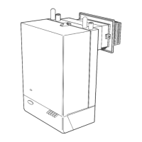
14 OVERHEAT THERMOSTAT REPLACEMENT Fitted for sealed systems only
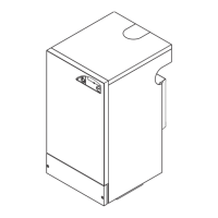
15 SPARK ELECTRODE AND LEAD
REPLACEMENT
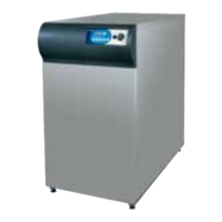
16 THERMOCOUPLE REPLACEMENT
1. Refer to Frame 8.
2. Remove the burner and air box assembly. Refer to
Frame 3.
3. Remove the electrode retaining nut. Refer to Frame 11.
4. Remove the pilot shield and electrode
5. Unscrew the central pilot fixing screw. Lift the pilot clear of
the thermocouple and pilot injector. Refer to Frame 11.
6. Withdraw the thermocouple and fit the replacement.
Re-assemble in reverse order, ensuring that no sharp
bends are used on the thermocouple and the pilot shield is
refitted.
7. Replace the boiler casing. Refer to Frame 6.
8. Check the operation of the thermocouple.
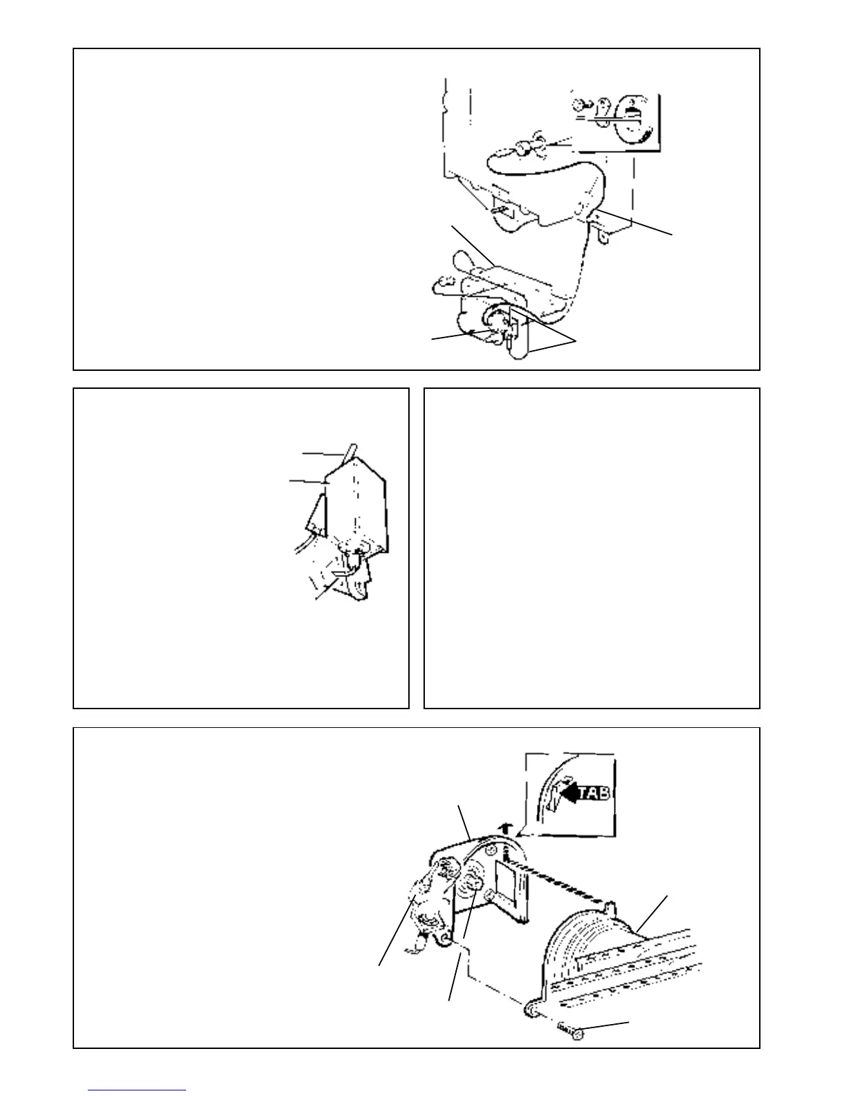
17 MAIN BURNER AND MAIN BURNER INJECTOR REPLACEMENT
DETAIL OF
LOCATION TAB
Main burner
injector
Pilot burner
Air box
assembly
DETAIL OF PILOT BURNER
DETAIL OF
OVERHEAT
THERMOSTAT
POCKET
Control box
Overheat
thermostat
Yellow leads, see note 5
Overheat
thermostat
capillary
1. Refer to Frame 8.
2. Slacken the screw at the thermostat pocket and withdraw
the phial from pocket.
3. Unclip the capillary from back panel.
4. In order to gain access to the back-nut retaining the
overheat thermostat remove the control box cover by
undoing the cover retaining screw (refer to Frame 12).
Remove the back-nut.
5. Remove thermostat from control box and
pull off the two yellow leads.
6. Re-assemble the new thermostat in reverse order
(polarity immaterial), ensuring that the alignment peg
on the thermostat sits in the small hole adjacent to the
main fixing hole.
7. Replace the control box cover.
8. Replace the boiler casing. Refer to Frame 6
Thermocouple
Pilot
shield
Spark electrode
Main burner
M5 pozi screw and
washer, see note 2
1. Refer to Frame 8.
2. Remove burner and
air box assembly
Refer Frame 3,
3. Remove the electrode
retaining nut.
4. Remove the pilot shield.
5. Remove the spark
electrode and
integral lead.
6. Fit the new electrode.
and lead in reverse order,
taking care to replace the pilot shield.
7. Check the spark gap. Refer to Frame 7.
8. Refit the burner.
9. Replace the boiler casing. Refer to Frame 6.
10. Check the pilot ignition.
1. Refer to Frame 8.
2. Remove the screw retaining the front of the burner
support bracket to the combustion chamber.
3. Remove the M5 pozi screw and washer, situated at
the left hand bottom rear of the burner. Pull the
burner downwards to disengage the retention tab
and remove the burner.
4. At this stage the main burner injector can be
removed, checked, cleaned or replaced as required.
Ensure that an approved jointing compound is used
sparingly.
5. Fit new burner, ensuring that the retention tab is
correctly located in the air box slot.
6. Refit the M5 retaining screw and washer.
7. Refit the front burner support bracket.
8. Refit boiler casing. Refer to Frame 6.
9. Check the burner for cross-lighting and flame
stability.
 Loading...