INSTALLATION
FLUE PACKS Note: All flue packs contain 2 sachets of sealant.
PACK B. Contains a balanced flue terminal suitable for wall thicknesses from 229 mm ( 9 in.) to 305 mm (12 in.)
PACK B1. Contains a balanced flue terminal suitable for wall thicknesses from 318 mm (12 1/2in.) to 394 mm (15 1/2in.)
PACK C. Contains a balanced flue terminal suitable for wall thicknesses from 114 mm ( 4 1/2in.) to 191 mm ( 7 1/2in.)
PACK D. Contains extension ducts which, when used in conjunction with PACK B, are suitable for wall thicknesses from
406 mm (16 in. ) to 584 mm (23 in.).
Note: Wall thicknesses outside those specified cannot be accommodated. An overlap of at least 50 mm at any duct joints must
be allowed
6
1. Unpack the boiler
2. Remove the casing as follows, and place to one side to avoid
damage.
(a) Release the controls pod fixing screws (a) 3 full turns only.
Remove the pod by pulling it forward to disengage from
the keyhole slots.
(b) Undo the 3 screws (b) retaining the casing to the back panel.
(c) Remove the casing in the direction of the arrows.
Controls
pod door
3. Fit the plastic controls pod door to the controls casing as
follows:
A. Insert the L.H. door catch into the L.H. metal clip, fitted
to the controls pod casing.
B. Push the R.H.door catch into the R.H. metal clip.
4. Unpack the flue terminal.
5. Remove the boiler from its packing base. Do not remove
the pod casing controls protection box.
Controls
pod casing
Metal clip
Packing base
Controls
pod
casing
1 A UNPACKING - continued
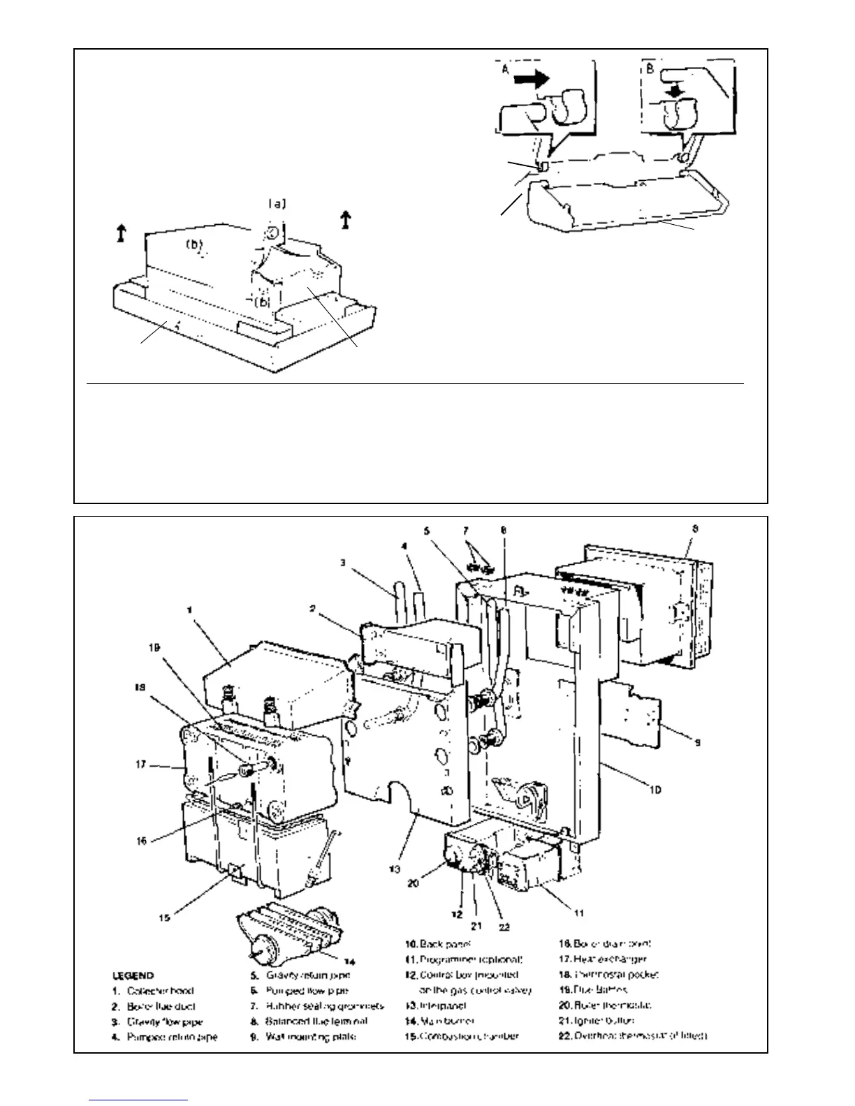
UNPACKING - BOILER ASSEMBLY
2 BOILER ASSEMBLY
Exploded view
 Loading...