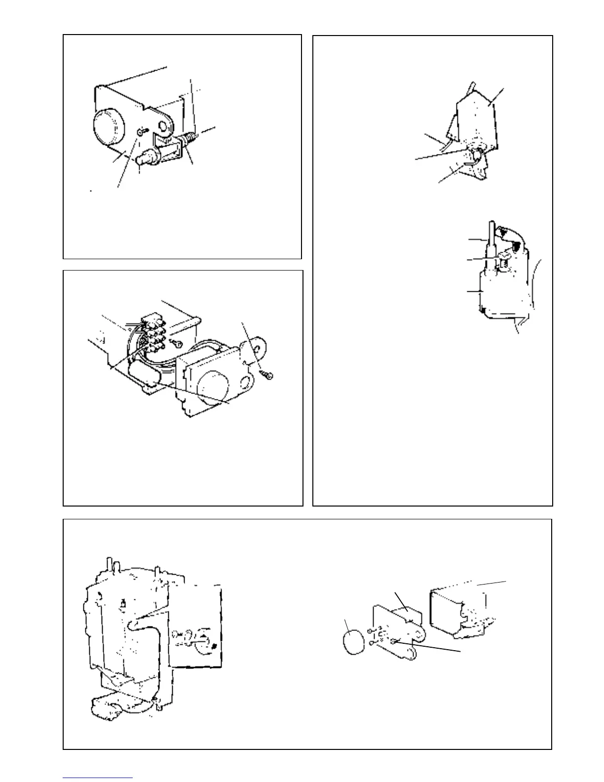
3. Remove
the suppressor
by removing the screw
retaining the terminal block, lifting the
terminal block and unscrewing the suppressor lead
connections
4. Fit the new suppressor and re-assemble in reverse order.
Ensure that all of the electrical connections are correctly
remade - refer to 'Wiring Diagrams'.
5. Replace the boiler casing. Refer to Frame 6.
6. Check the operation of the control thermostat.
17
REPLACEMENT OF PARTS
11 PILOT BURNER REPLACEMENT
13 CONTROL THERMOSTAT REPLACEMENT
6. Pull off the two electrical connections from the thermostat
head and the thermostat earth lead.
7. Fit the new thermostat and refit in reverse order. Ensure
that the phial is correctly replaced in the pocket and the
capillary routed as previously.
8. Replace the boiler casing. Refer to Frame 6.
9. Check the operation of the new thermostat. Refer to
Frame 25 'Installation.'
4. Pull off the thermostat knob. Remove the control box cover
retaining screw and remove the cover, complete with
thermostat.
5. Remove the two screws securing the thermostat.
Thermostat
knob
Control
box
Control thermostat
Control box cover
retaining screw
Ensure that the copper sealing
washer is fitted when replacing
the injector.
Electrode retaining
nut, see note 3
Electrode
Pilot
shield
Thermocouple
Fixing screw,
see note 4
Pilot burner
Piezo unit
SERVICING
10 PIEZO UNIT REPLACEMENT
2. Disconnect the ignition
and earth leads from
the piezo unit.
3. Unscrew the locking
nut at the rear of the
piezo unit mounting
bracket.
12 SUPPRESSOR REPLACEMENT
1. Refer to Frame 8.
Terminal strip
Suppressor
2. Remove the screw retaining
the control box cover and
remove the cover, c/w
thermostat.
1. Refer to Frame 8.
Control box
5. Replace the pilot burner and retain with the M4 screw
previously removed.
6. Replace the electrode and pilot shield - retaining both with
the electrode nut.
7. Replace the airbox assembly and ensure that the gasket is
in position.
8. Replace the burner.
9. Check the pilot burner relationship to the main burner and
spark gap. Refer to Frame 7.
10. Replace the boiler casing. Refer to Frame 6.
11. Check the pilot length. Refer to Frame 7.
12. Check the pilot operation (cross lighting, holding in time,
etc.).
If required, the pilot
injector may now
be unscrewed and
the injector
checked or
replaced as
necessary.
4. Unscrew the central pilot fixing screw and lift the pilot clear
of thermocouple and pilot injector.
3. Remove the electrode
retaining nut. Remove
the pilot shield and
electrode.
1. Refer to Frame 8.
2. Remove burner and air box assembly. Refer to Frame 3.
Thermocouple
DETAIL
OF
THERMOSTAT
POCKET
Control box
Securing
screw, see
note 3
Thermostat capillary
1. Refer to Frame 8.
2. Unclip the thermostat capillary from the two clips
situated on the back panel
3. Slacken the screw at the thermostat pocket
retaining screw.
4. Remove the control box cover.
5. Remove the piezo unit.
Refit the new unit and re-assemble in reverse order.
6. Replace the boiler casing - Frame 6.
7. Check the operation of the new piezo unit.
 Loading...