5 CLEANING THE BURNER AND PILOT ASSEMBLY
Refer to Frame 3 for illustration of the procedure below.
1. Brush off any deposits that may have fallen onto the burner
head, ensuring the flame ports are unobstructed, and
remove any debris that may have collected.
Note: Brushes with metallic bristles MUST NOT be used.
2. Remove the main burner injector and ensure that there is
no blockage or damage.
3. Refit injector using an approved jointing compound
sparingly.
4. Inspect the pilot burner, thermocouple and spark electrode;
ensure they are clear and in good condition. Check that:
(a) The pilot burner injector is not blocked or damaged
(refer Frame 11 for removal details).
CLEANING AND ADJUSTMENT - REPLACEMENT OF PARTS
6 RE-ASSEMBLY
(b) The pilot burner is clean and unobstructed.
(c) The spark electrode is clean and undamaged.
(d) The spark lead is in good condition and securely
connected.
(e) The spark gap is correct. Refer Frame 7.
(f) The thermocouple tip is not burned or cracked.
(g) The position of the thermocouple relative to the pilot
burner and main burner is correct. Refer to Frame 7.
(h) The thermocouple terminal at the gas valve is clean.
5. Re-assemble the burner / air box assembly in reverse
order. Ensure that the burner tab is correctly located.
Refer to Frame 3
Note: The pilot shield is positioned around the pilot assembly
bracket and is located by the electrode retaining nut
7 PILOT BURNER SETTING
3. Refit the burner and air box assembly.
4. Turn on the gas supply
5. Ensure the sightglass in the boiler casing is clean and
undamaged .
6. Refit the boiler casing and tighten the three captive screws.
7. Inspect the visible casing seal for correct fit.
8. Refit control casing pod (see Frame 1 Inst.-note 2a)
9. Close the controls pod door.
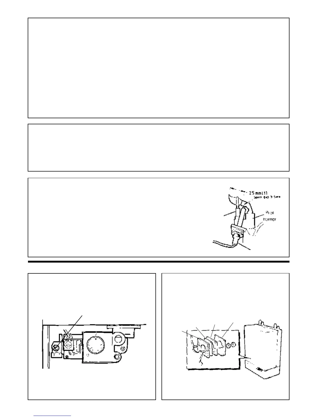
DETAIL OF PILOT BURNER FLAME LENGTH
16
REPLACEMENT OF PARTS
9 SIGHTGLASS REPLACEMENT
1. Refer to Frame 8.
2. Unfasten the two nuts and washers holding the sightglass
assembly to the casing front panel.
3. When fixing the new assembly, make certain that the parts
are in the correct order. The frame MUST have the return
edge at the bottom.
Frame
Gasket
Glass
8 GENERAL
The boiler MUST NOT be operated if the casing is not fitted.
IMPORTANT. When work is complete the casing MUST be
correctly refitted - ensuring that a good seal is made.
(c) Remove the boiler casing (refer to Frame 2).
(a) Isolate the electricity supply.
(b) Turn off the gas supply at the boiler - refer to the
illustration below.
When replacing any component:
Note: The gas cock is shown in the CLOSED position.
Gasket
SERVICING
Re-assemble in reverse order to that shown in Frames 2 to 5.
1. Refit the flue baffles and retain with the spring clips.
2. Refit the collector hood, replacing any damaged or
deteriorating gaskets. Note: Ensure rear vertical hood
retaining screws are tightened before rear horizontal
screws.
1. Turn on the gas supply.
2. Light the pilot (refer to Frame 23 'Installation') and check that the pilot flame
envelopes the tip of the thermocouple and is approximately 25 mm (1 in.) long.
The pilot is factory set to maximum and no further adjustment should be necessary.
However, if the pilot flame appears small, check the pilot injector. Refer to
Frame 11.
Electrode
Thermocouple
4. Retighten the two nuts to ensure an airtight seal.
Do NOT overtighten
5. Replace the boiler casing - refer to Frame 6.
After each occasion of servicing, reference should be made to Table 2, which quotes
details of the rated output, with the related burner setting pressure and the heat input.
Any required adjustment should be made by using the pressure adjustment screw. .
Refer to Frame 23, 'Installation'.
Heat Input / Setting Pressure
 Loading...