SERVICING
1 SCHEDULE
GENERAL - CLEANING AND ADJUSTMENT
2 BOILER CASING REMOVAL
To ensure the continued safe and efficient operation of the
appliance, it is recommended that it is checked at regular
intervals and serviced as necessary. The frequency of
servicing will depend upon the installation condition and usage,
but should be carried out at least annually .
It is the law that any service work must be carried out by a
competent person.
(a) Light the boiler and carry out a pre-service check, noting
any operational faults.
(b) Clean the main burner.
(c) Clean the heat exchanger.
(d) Clean the main and pilot injectors.
(e) Check that the flue terminal is unobstructed and that the
flue system, including the inner cover, is sealed correctly.
(f) If the appliance has been installed in a compartment, check
that the ventilation areas are clear.
The servicing procedures are covered more fully in Frames 2
to 7 and must be carried out in sequence.
WARNING. Disconnect the electrical supply.
IMPORTANT. After completing the servicing or exchange of
components always test for gas soundness and carry out
functional checks as appropriate.
Note. In order to carry out either servicing or replacement of
components, the boiler casing must be removed (Frame 2).
IMPORTANT. When work is complete the casing MUST be
correctly refitted, ensuring that a good seal is made.
The boiler must NOT be operated if the casing is not fitted.
1. Refer to Frame 1.
2. If the Ideal Classic sealed system module is fitted lift off
the casing to expose the boiler casing top fixing screw.
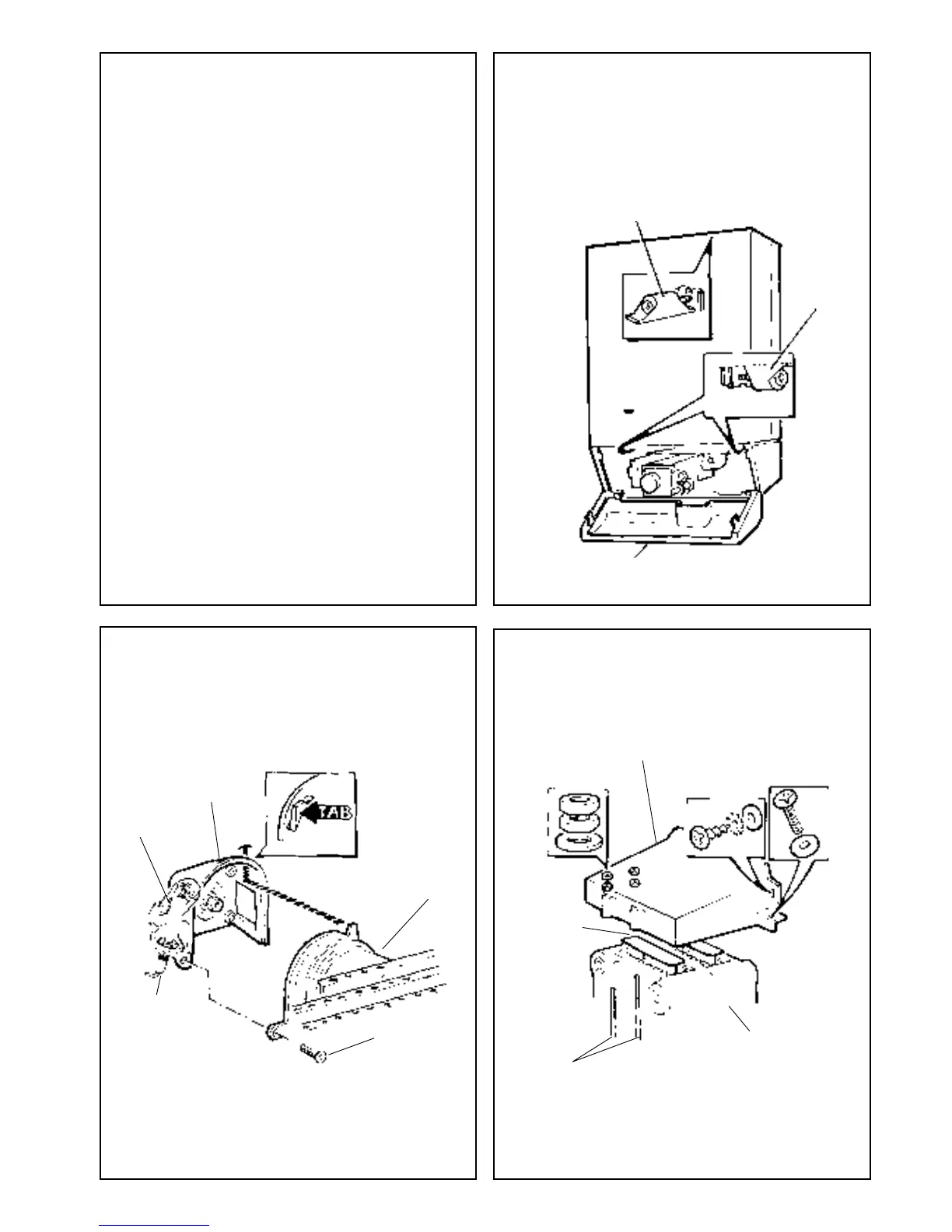
3. Open the controls pod door.
4. Release the three captive screws at the top and bottom of
the casing. Lift the casing off the boiler and retain in a safe
place .
3 BURNER AND AIR BOX REMOVAL
1. Remove the screw retaining the front burner support
bracket to the combustion chamber.
2. Remove the M5 pozi screw situated at the left hand,
bottom rear of the burner and pull the burner downwards
in order to disengage the retention tab. Remove burner to
a safe place for inspection and cleaning.
3. Unscrew the thermocouple connection at the gas control.
4. Remove the four screws retaining the air box / pilot
assembly to the vertical manifold.
5. Pull off the electrode lead at the piezo unit.
6. Unhook the clip retaining the thermocouple and H.T. lead.
Remove the air box assembly to a safe place for
inspection and cleaning.
15
4 CLEANING THE FLUEWAYS
Thermocouple
Air box
See note 1
M5 pozi screw,
see note 1
3. Unclip and remove the flue baffles from the heat
exchanger.
4. Remove all loose deposits from the heat exchanger,
particularly between the fins, using a suitable brush or rod.
1. Remove the collector hood by undoing the front tie rod
double nuts and washers. Withdraw the rods.
2. Remove the 4 collector hood retaining screws and
washers
Heat exchanger
Collector hood
Flue baffles
Tie rods
5. Isolate the gas supply at the service cock. Refer to Frame 8.
Controls pod door
Bottom
captive
screws,
2 off
Top captive screw, 1 off
Main burner
Electrode
 Loading...