INSTALLATION
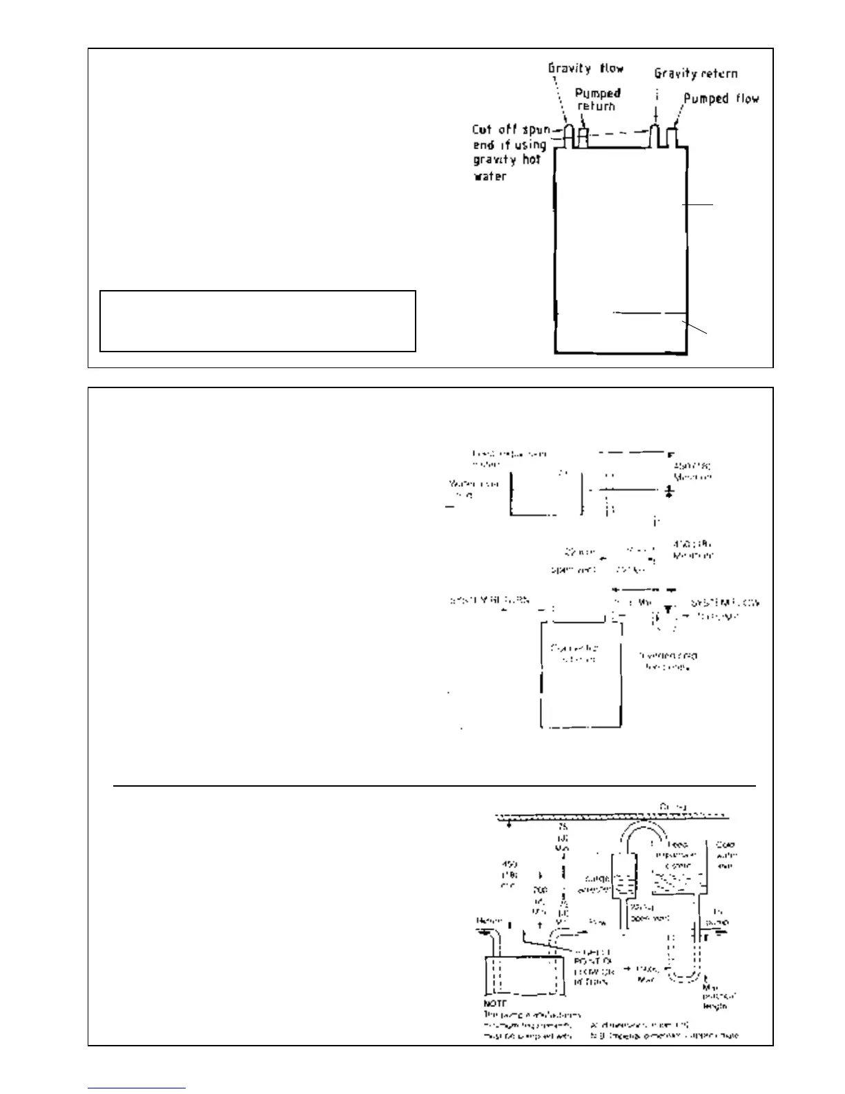
3 BOILER WATER CONNECTIONS. Open vented systems.
SYSTEM DESIGN
1. This appliance is NOT suitable for use in a direct hot water
system
2. If the boiler is to be used on a sealed system an overheat
thermostat kit is available and must be installed, in
accordance with the instructions supplied with the kit.
3. If the boiler is to be used for gravity domestic hot water
supply then cut off the spun ends of the gravity flow and
return pipes and fit a 22 mm to 28 mm copper connection
at the boiler gravity flow and return connections in order to
run the gravity circuits in 28 mm pipe.
4 OPEN VENT SYSTEM REQUIREMENTS. Fully pumped.
LOW HEAD INSTALLATIONS
Ensure that the
pipes are 50 mm
long - measured
from the top of
the boiler casing
if capillary
fittings are used
- or 35mm long if
compression
fittings are used.
Boiler
casing
Controls
pod door
All dimensions in mm. (in.)
MINIMUM REQUIREMENT
The system should be vented directly off the boiler flow pipe, as
close to the boiler as possible. The cold feed entry should be
inverted and MUST be positioned between the pump and the vent,
and not more than 150 mm (6 in.) away from the vent connection.
Note: Alternatively, the redundant gravity flow and return
connections may be used for feed and vent if a close coupled feed
and vent system is not desired
There should be a minimum height - 450 mm (18 in.) of open vent
above cistern water level. If this is impossible refer below.
The vertical distance between the highest point of the system
and the feed/expansion cistern water level MUST not be less
than 450 mm (18 in.). The pump MUST be fitted on the flow side of
the boiler.
A suitable pump is a domestic circulator capable of providing an
11°C (20°F) temperature differential (e.g. Grundfos UPS 15 /50 or
equivalent). The vertical distance between the pump and feed /
expansion cistern MUST comply with the pump manufacturer's
minimum requirements to avoid cavitation. Should these
conditions not apply, either lower the pump position or raise the
cistern above the minimum requirement specified by Caradon
Ideal Ltd. Note: A cold water feed path must be available back to
the boiler, when all automatic valves are in the closed position
(refer BS.6798) and when close coupled the feed must not be in a
vertical leg.
All dimensions in mm. (in.)
The Ideal Classic range of boilers can be installed in low head
situations by fitting a 'surge arrester' in the expansion pipe - as shown.
The following conditions MUST be observed;
1. The surge arrester must be at least 42 mm in diameter
x 150 mm long, thus ensuring a MINIMUM air gap and a
MINIMUM depth of water below the static water level (cold ) of
75 mm.
2. The static water level (cold) must be at least 200 mm above the
top of the horizontal flow pipe, fitted as shown. The vent
connection MUST NOT be made immediately off the top of the
boiler, as venting is made less efficient.
3. The maximum practical length of 15 mm cold feed pipe should be
used in order to reduce the effective volume of system water
expanding into the feed / expansion cistern
For Sealed System applications (fully pumped) refer to the
Overheat Thermostat Kit instructions
7
 Loading...