SYSTEM DESIGN - BOILER DIMENSIONS & CLEARANCES
INSTALLATION
5 REQUIREMENTS FOR CORRECT GRAVITY HOT WATER PERFORMANCE
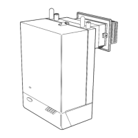
7 CLEARANCES & TERMINAL OPENING
1. Tape the template to the wall in the selected position.
Ensure squareness by use of a plumbline - as shown.
2. Mark out the position
of the 3 wallplate
screws, choosing 1
from each group of 3
holes. Also mark the
position of the hole
for the duct, the
jacking plate screw
and the top cover
plate screws.
3. Drill the three holes,
8 mm (5/16 in.), and
insert the 3 plastic
plugs. Also drill the
jacking plate screw
and the top cover
plate screw holes and
insert the plastic
plugs.
8
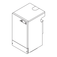
6 BOILER DIMENSIONS / SERVICES
All dimensions in mm (in.)
4. Remove the template from the wall.
8 WALL MOUNTING TEMPLATE
NOTE: Gravity horizontal pipes should be ABOVE ceiling level and
as SHORT as possible. A MINIMUM inclination of 25 mm per 3 m
run (1 in per 10 ft.) is required to avoid air locks. If these conditions
cannot be met, pumped primaries MUST be used.
The above graph assumes 8 elbows in the gravity circuit. For each
elbow in excess of 8, (R) must be reduced by 300 mm (12 in.) or
(H) increased by 100 mm (4 in.)
1
Front clearance
from the front of
the boiler casing.
These are the
minimum
clearances
needed to allow
access to service the boiler, but additional space may be needed
for installation, depending on site conditions. Note: If using the
sealed system module, refer to the instructions packed with the
module for the necessary clearances.
 Loading...