GENERAL
An existing meter should be checked, preferably by the gas
region, to ensure that the meter is adequate to deal with the
rate of gas supply required.
Installation pipes MUST be fitted in accordance with BS. 6891.
Pipework from the meter to the boiler MUST be of an adequate
size. Do NOT use pipes of smaller size than the boiler inlet gas
connection.
The complete installation MUST be tested for gas soundness
and purged as described in the above Code.
FLUE INSTALLATION
The flue must be installed in accordance with the
recommendations of BS. 5440:1
The following notes are intended tor general guidance:
1. The boiler MUST be installed so that the terminal is
exposed to external air.
2. It is important that the position of the terminal allows the
free passage of air across it at all times.
3. Minimum acceptable spacings from the terminal to
obstructions and ventilation openings are specified in
Table 3.
4. Where the lowest part of the terminal is fitted less than
2 m (6.6 ft.) above a balcony, above ground or above a
flat roof to which people have access then the terminal
MUST be protected by a purpose designed guard.
Terminal guards are available from:
Quinnel, Barret & Quinnel Ltd.,
884 Old Kent Road, London SE15 (Model P6) and
Tower Flue Components Ltd.,
Vale Rise, Tonbridge, Kent. TN9 1TB (Model C).
Ensure that the guard is fitted centrally.
5. Where the terminal is fitted within 850 mm (34 in.) of a
plastic or painted gutter or 450 mm (18 in.) of painted
eaves then an aluminium shield at least 750 mm (30 in.)
long should be fitted to the underside of the gutter or
painted surface.
6. The air inlet/products outlet duct and the terminal of the
boiler MUST NOT be closer than 25 mm (1 in.) to
combustible material. Detailed recommendations on the
protection of combustible material are given in
BS. 5440:1, 1990.
IMPORTANT. It is absolutely ESSENTIAL to ensure, in
practice, that products of combustion discharging from the
terminal cannot re-enter the building or any other adjacent
building through ventilators, windows, doors, other sources
of natural air infiltration or forced ventilation/ air-
conditioning.
If this should occur, the appliance MUST be turned OFF
immediately and the local gas region consulted.
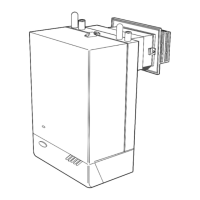
TERMINAL
The terminal assembly can be adapted to accommodate
various wall thicknesses. Refer to Frame 1 'Unpacking'.
AIR SUPPLY
Detailed recommendations for air supply are given in
BS.5440:2. The following notes are for general guidance:
1. It is NOT necessary to have a purpose provided air vent
in the room or internal space in which the boiler is
installed .
2. If the boiler is to be installed in a cupboard or compartment,
permanent air vents are required (for cooling purposes) in
the cupboard/ compartment, at both high and low levels.
The air vents must either communicate with room/internal
space or be direct to outside air. The minimum effective
FLUE INSTALLATION - AIR SUPPLY
4
areas of the permanent air vents required in the cupboard/
compartment are specified as follows and are related to
maximum rated heat input.
3. Both air vents MUST communicate with the same room or
internal space or MUST be on the same wall to outside air.
4. In siting the air vents care must be taken to avoid the
freezing of pipework.
Refer to Tables 4 - 7 for details of air vent positioning and
sizing.
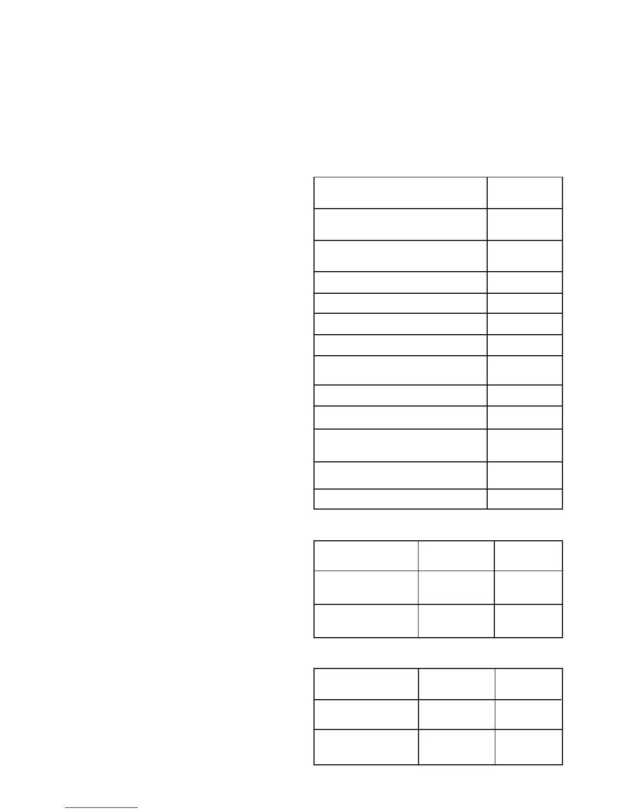
Table 3 - BALANCED FLUE TERMINAL POSITION
Terminal Position Minimum
Spacing
1. Directly below an opening window,
air vent or other ventilation opening 300 mm (12 in.)
2. Below guttering, drain pipes or soil
pipes 300 mm (12 in.)
3. Below eaves 300 mm (12 in.)
4. Below balconies or a car port roof 600 mm (24 in.)
5. From vertical drain pipes or soil pipes 75 mm (3 in.)
6. From internal or external corners 600 mm (24 in.)
7. Above adjacent ground, roof or
balcony level 300 mm (12 in.)
8. From a surface facing the terminal 600 mm (24 in.)
9. From a terminal facing a terminal 600 mm (24 in)
10. From an opening in a car port
(e.g. door or window) into dwelling 1200 mm (48 in)
11. Vertically from a terminal on the same
wall 1500 mm (60 in)
12. Horizontally from a terminal on the wall 300mm (12 in.)
Table 4 - RS 30 AIR SUPPLY
Position of air vent Air from room/ Air direct
internal space from outside
HIGH LEVEL cm
2
102 51
(in
2
) (16) (8)
LOW LEVEL cm
2
102 51
(in
2
) (16) (8)
Table 5 - RS 40 AIR SUPPLY
Position of air vent Air from room/ Air direct
internal space from outside
HIGH LEVEL cm
2
135 68
(in
2
) (21) (11)
LOW LEVEL cm
2
135 68
(in
2
) (21) (11)
 Loading...