Ideal offers the following kit:-
(see kit for installation instructions)
Weather Compensation Kit: allows outside temperature sensing.
2.18 OPTIONAL SYSTEM CONTROLS KITS
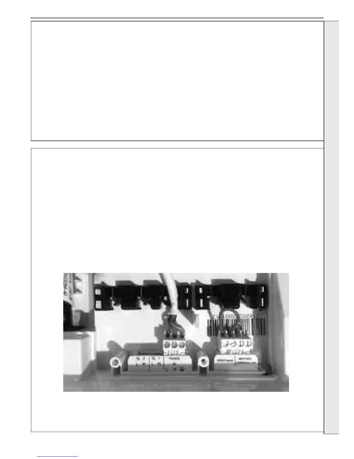
The Vogue System GEN2 boiler comes pre-tted with a red link wire between the SL1 connections and a violet link wire
between the OpenTherm connections of the installer wiring connections. This creates a permanent call for heat and the
appropriate link must be removed when adding a Room Thermostat/Timer. For 230V remove the SL1 link, for PELV remove the
2.19 INTERNAL WIRING - EXTERNAL CONTROLS
OpenTherm link
To add wired external Room Thermostats, Timers or
Programmers proceed as follows:-
1. Isolate the mains supply to the boiler.
2. Remove the front panel (refer to Section 3.2).
3. Swing the control box down into the servicing position
(refer to Section 3.3).
4. Route incoming cables through the grommets in the
bottom panel (note: grommets are ‘blind’ and will require
puncturing) and secure using clamps and screws provided
in the hardware pack.
5. Remove the installer wiring cover.
6. Connect wires to the appropriate plug, which may be
removed to aid wiring.
7. Re-assemble in reverse order.
WARNING: UNDER NO CIRCUMSTANCES MUST A 230V CONNECTION
BE MADE TO THE OPENTHERM OR WEATHER COMPENSATION CONNECTIONS
INSTALLATION
 Loading...