3.10 REPLACEMENT OF COMPONENTS
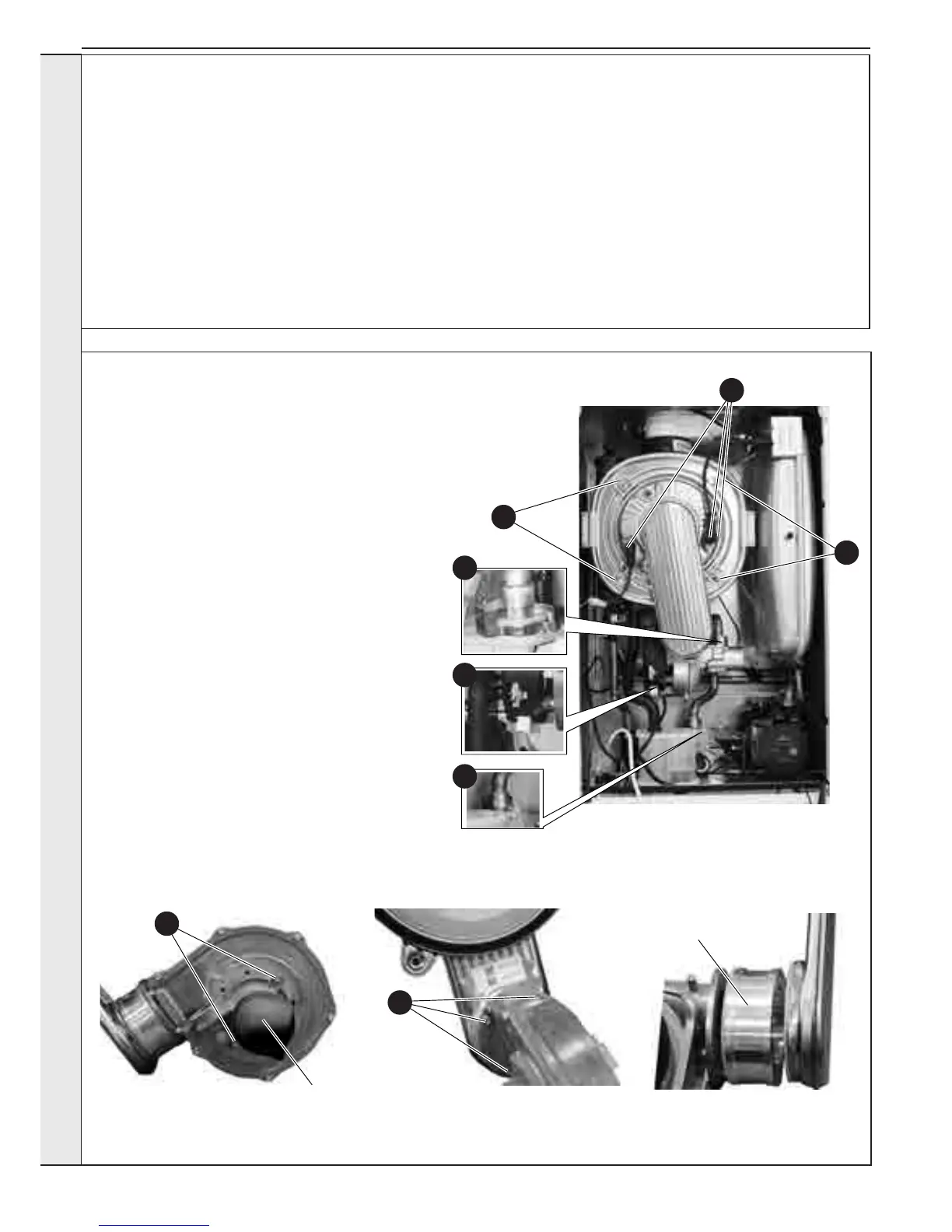
3.11 FAN REPLACEMENT
1. Refer to Sections 3.2 & 3.3.
2. Remove the ignition, detection and earth leads.
3. Remove the 2 clips securing the gas inlet pipe and
remove the pipe.
4.
Remove the fan low voltage and mains connections.
5. Remove the 4 securing nuts retaining the burner/fan
assembly.
6. Remove the assembly from the heat exchanger.
7. To remove the venturi release the 2 securing screws to
gain access for cleaning.
8. When replacing check the sealing gasket is
undamaged or replace as necessary, and secure with
the 2 screws.
9. To remove the fan, rst remove the venturi as above
and release the 3 screws securing the fan to the burner.
(Note a mounting spacer is tted to the fan outlet on
32kW model only)
10. Replace the fan and ret the venturi checking the
sealing gasket is undamaged or replace as necessary,
and secure with the 2 screws
*Note a noise damper is tted to the venturi inlet on the
32kW models
*Note a mounting spacer is tted to the fan outlet on
32kW.
11. Check the operation of the boiler. Refer to Sections
2.24 - 2.27.
When replacing ANY component:
1. Isolate the electrical supply
2. Isolate water connections
3. Turn off the gas supply
4. Remove the front panel
5. Swing the control panel down into the service position
After replacing ANY component check operation of the boiler,
2
3
5
5
7
Noise Damper
Fitted only to
32kW model
Mounting Spacer
Fitted only to
32kW model
9
including gas tightness, gas rate and combustion
test.
IMPORTANT. when work is complete, the front
panel must be correctly retted - ensuring that a
good seal is made.
THE BOILER MUST NOT BE OPERATED
WITHOUT THE FRONT PANEL FITTED.
4
3
SERVICINGSERVICING
 Loading...