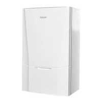
3.26 PUMP HEAD REPLACEMENT
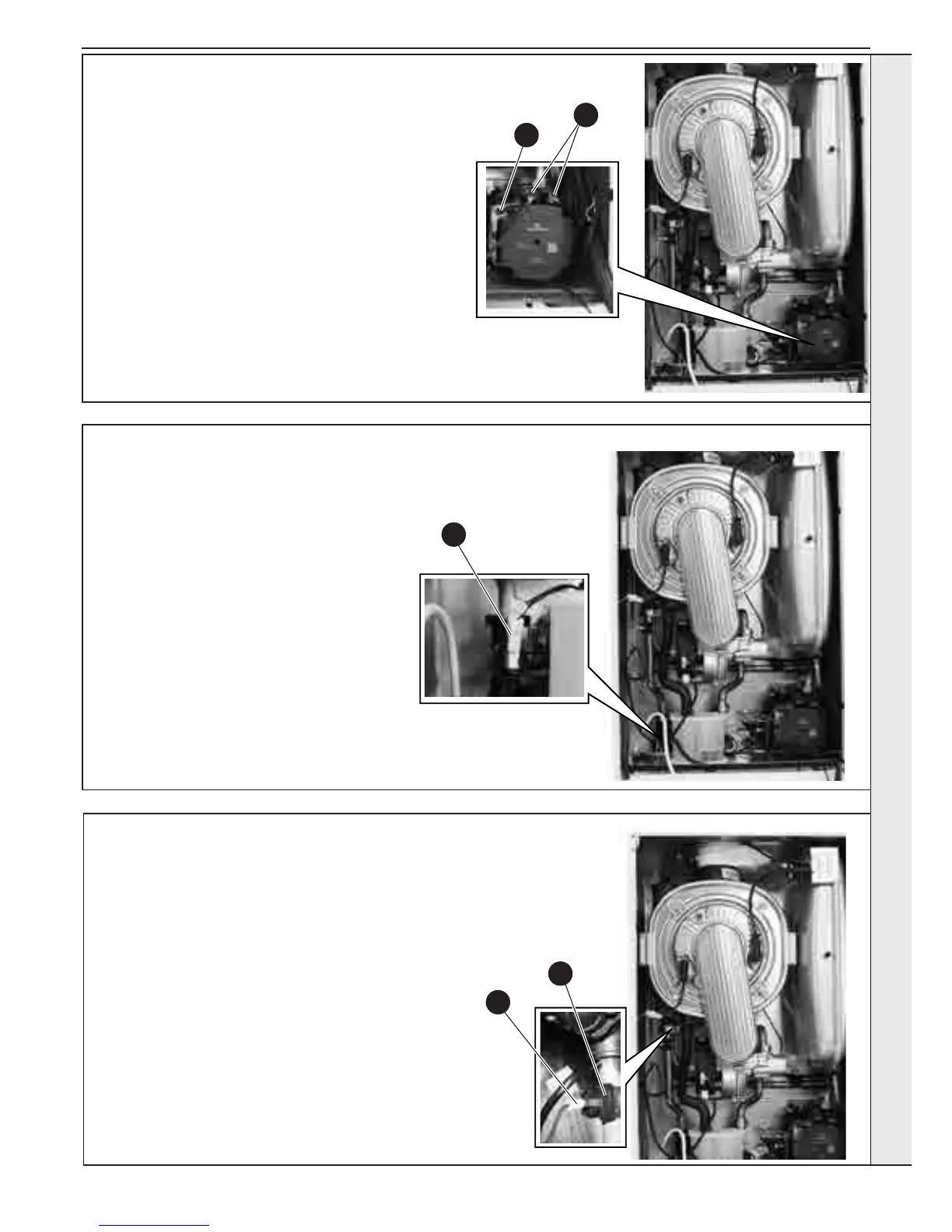
3.27 CH WATER PRESSURE SENSOR REPLACEMENT
1. Refer to Sections 3.2 & 3.3.
2. Close the isolating service valves and
drain the (CH) boiler. Refer to Section
3.22.
3. Disconnect both electrical leads to the
pump.
4. Remove the 4 Allen screws securing the
pump head and remove.
5. Ret in reverse order.
6. Open the isolating valves and rell the
CH system. Refer to Section 2.15.
7. Check the operation of the boiler. Refer
to Sections 2.24 - 2.27.
1. Refer to Sections 3.2 & 3.3.
2. Close the isolating service valves and drain
the (CH) boiler. Refer to Section 3.22.
3. Remove the condensate trap. Refer to
Section 3.19.
4. Remove the retaining clip to the rear of the
housing.
5. Pull out the sensor and disconnect the
electrical connection.
6. Ret in reverse order.
7. Open the isolating valves and rell the CH
system. Refer to Section 2.15.
8. Check the operation of the boiler. Refer to
Sections 2.24 - 2.27.
3.28 FLOW THERMISTOR REPLACEMENT
1. Refer to Sections 3.2 & 3.3.
2. Unclip the ow thermistor.
3. Disconnect the electrical lead from the thermistor.
4. Reconnect the electrical lead to the new thermistor and
reassemble in reverse order, ensuring that the thermistor
is securely tted to the pipe on the thermistor locator tabs
as shown.
5. Check the operation of the boiler. Refer to Sections 2.24
- 2.27.
3
4
4
3
5
SERVICING
 Loading...