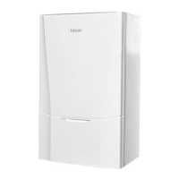
3.24 SAFETY PRESSURE RELIEF VALVE RENEWAL
1. Refer to Sections 3.2 & 3.3.
2. Close the isolating service valves
and drain the (CH) boiler. Refer to
Section 3.22.
3. Remove the burner & Fan assembly,
if required for access. Refer to
Section 3.4.
4. Undo the Safety Relief Valve outlet
retaining nut. (retaining the washer)
5. Remove the securing clip at the rear
of the valve body.
6. Withdraw the valve vertically.
7. Renew the valve and ret in reverse
order.
8. Rell the CH system. Refer to
Section 2.15.
9. Check the operation of the boiler.
Refer to Sections 2.24 - 2.27.
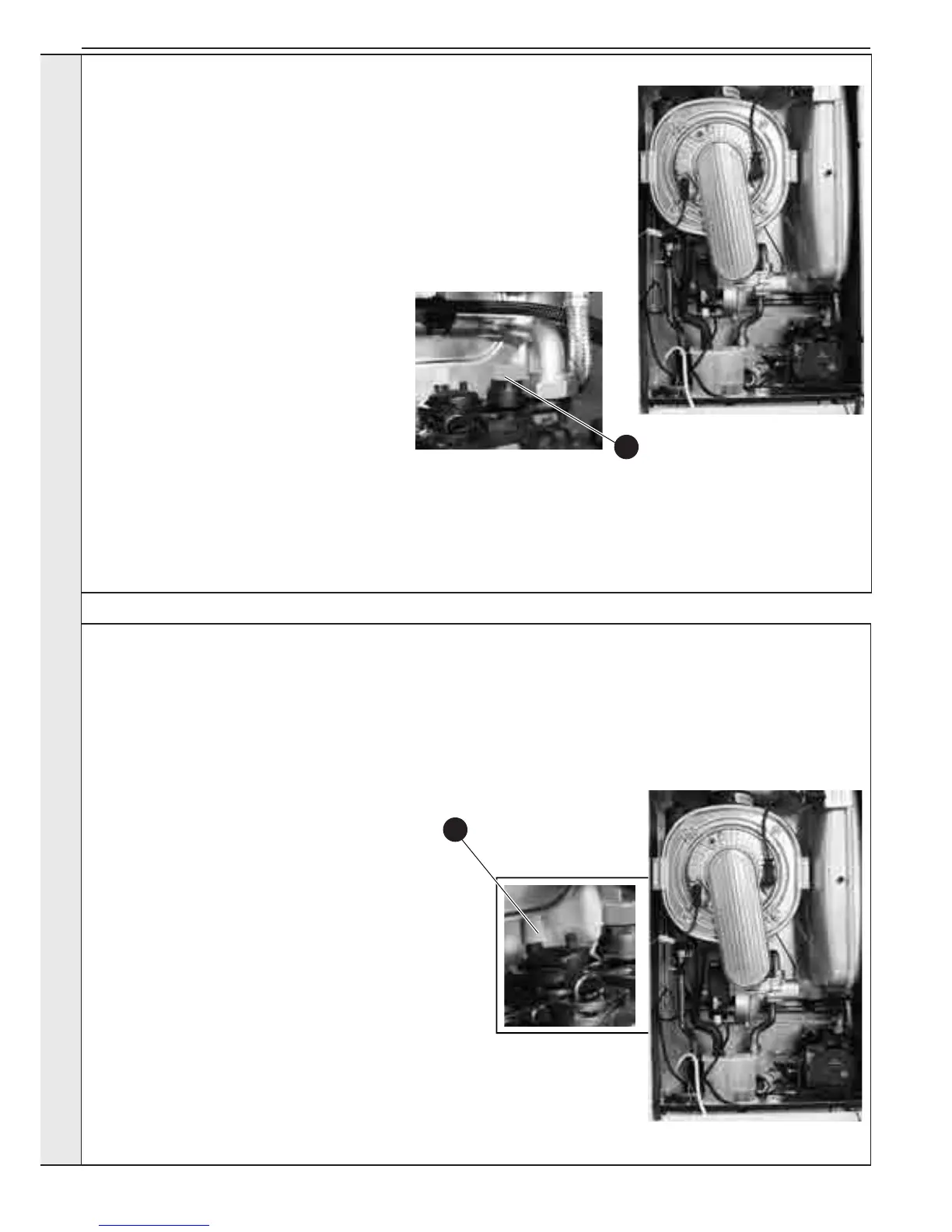
3.25 PUMP AUTO AIR VENT REPLACEMENT
1. Refer to Sections 3.2 & 3.3.
2. Close the isolating service valves and drain the
(CH) boiler. Refer to Section 3.22.
3. Remove the burner & Fan assembly, if required
for access. Refer to Section 3.4.
4. The auto air vent is retained in the pump body
with a bayonet connection. The air vent and
oat assembly is removed by turning the head
anti-clockwise (viewed from above) and pulling
upwards.
5. Ensure the air vent head o ring seal is in place
when retting and the seal is in place at the pump
outlet connection.
6. Reassemble in reverse order.
7. Rell the CH system. Refer to Section 2.15.
8. Loosen the cap of the air vent.
9. Check the operation of the boiler. Refer to
Sections 2.24 - 2.27.
4
6
SERVICING
 Loading...