9
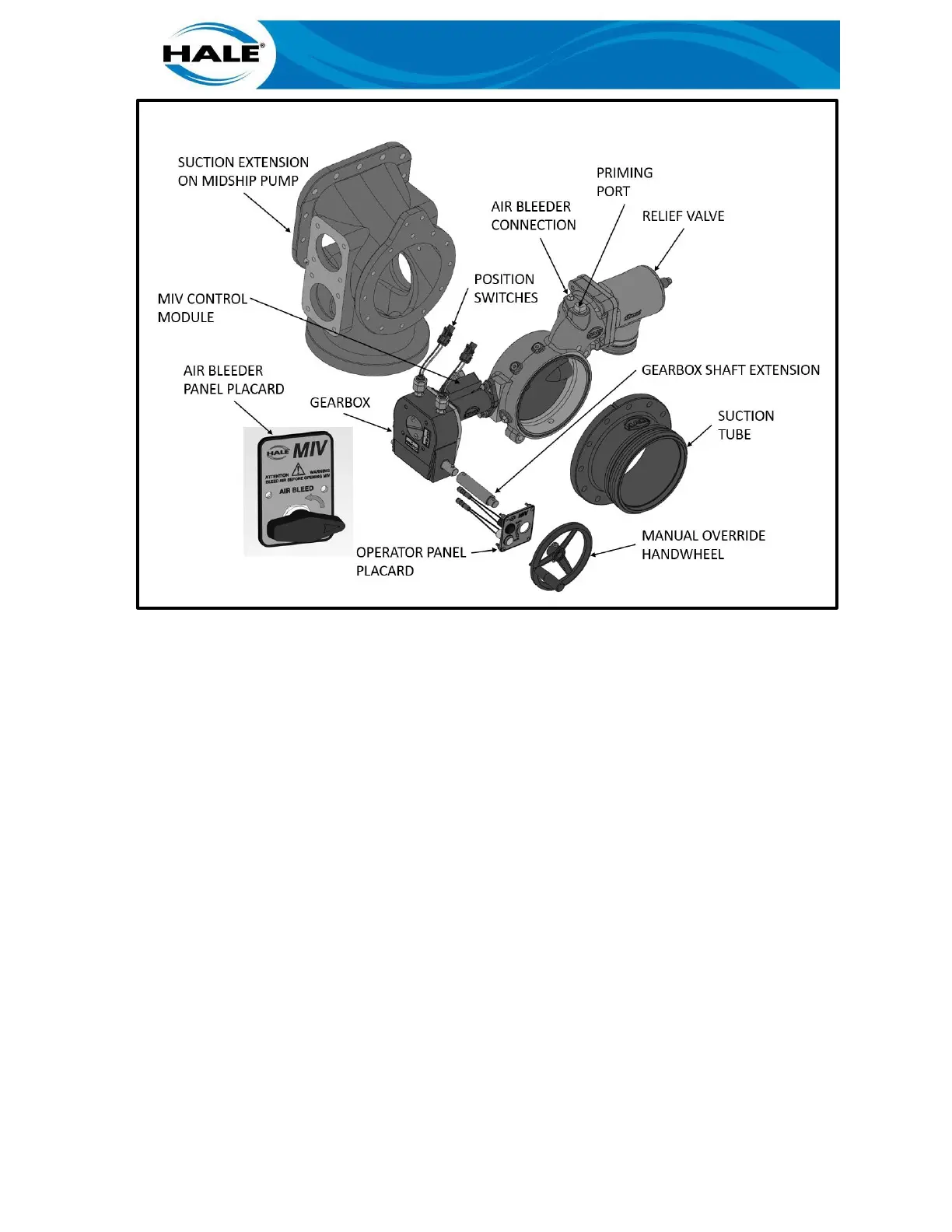
Figure 2. Component Part Identification (Manual Valve)
Bottom mounted valves are installed to bottom of the suction tube extension for use with front
and/or rear suctions (Figure 4).
The valve may also be installed in-line or it may be used with large auxiliary pumps. Optional Hale
6-inch NPT threaded flanges are available for use in these installations.
Whether installing the valve during new construction or installing the valve as a retrofit proper
planning and equipment layout will ensure smooth installation. The Hale MIV has been designed
to mount onto a Hale midship pump without interference to other suction and discharge connec-
tions on the pump. The plate drawing, FSG-PL-01491, provides the overall mounting dimensions
for various configurations of the Hale MIV.
When ordered as part of a new midship fire pump the valve will be pre-installed on the fire pump
and tested at the factory per NFPA requirements. When installing the midship pump on the appa-
ratus it will be necessary to install the relief valve discharge piping, air bleeder, suction hose
priming and drain valve (steps 2.2.3 through 2.2.9 in this section).
2.2.1 Mounting of Side Suction Valves
NOTE
WHEN INSTALLING THE HALE MIV AS A RETROFIT IT IS HIGHLY RECOMMENDED THAT
THE STANDARD SUCTION EXTENSION BE REPLACED WITH THE HALE P/N 178-0063-
00-0 SUCTION EXTENSION. THIS IS ESPECIALLY IMPORTANT ON APPARATUS WITH
PANEL WIDTHS OF 70, 72 AND 74 INCHES TO MINIMIZE PANEL MODIFICATION RE-
QUIRED. REFER TO MIV PARTS MANUAL, FSG-MNL-00218, FOR MOUNTING DIMEN-
SION DRAWINGS FOR ASSISTANCE IN PLANNING RETROFIT INSTALLATIONS.
 Loading...