15
4.
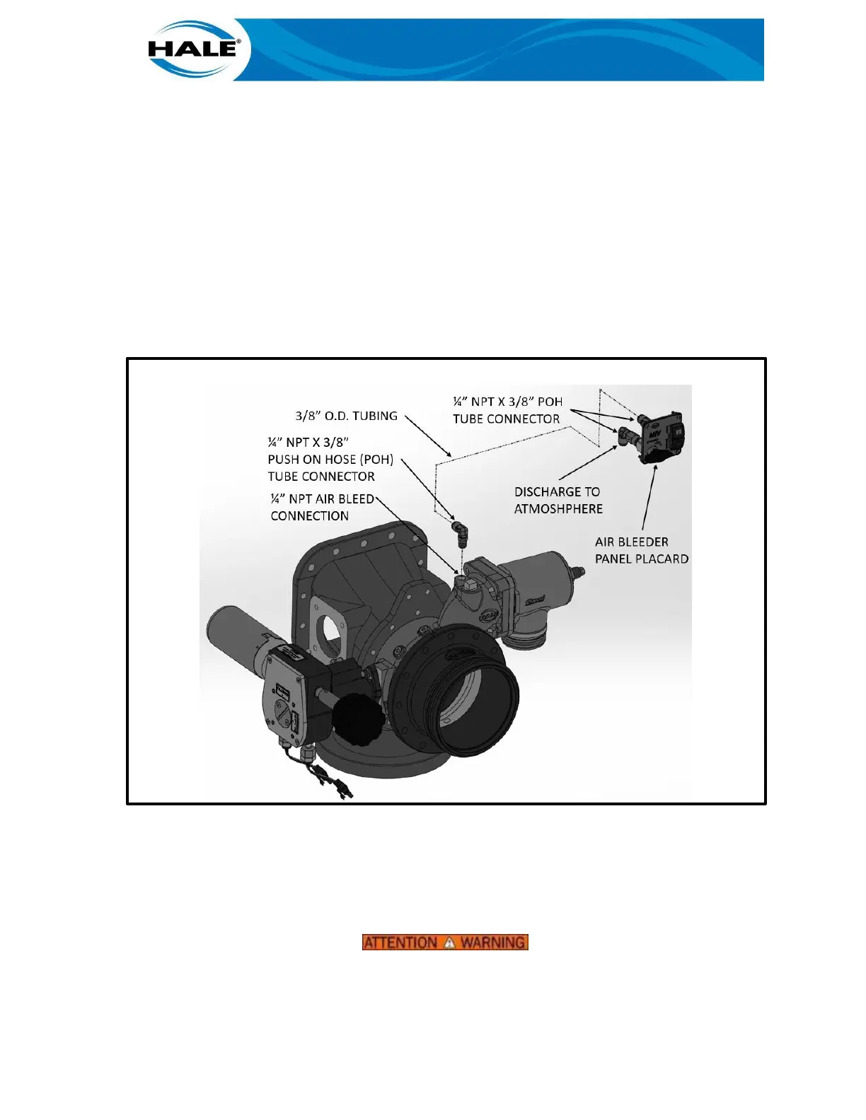
Install the ¼ inch NPT X 3/8 inch tube push on elbow into the hex outlet of the air bleeder
valve. To prevent damage to the valve body, hold the hex outlet on the valve with a wrench
while tightening elbow. Make sure the outlet of the elbow is facing away from the valve
handle.
5.
Using a 3/32 inch Allen wrench, loosen the setscrew and remove the valve handle from
the valve body.
6.
Remove the retaining nut from the valve body.
7.
Insert the valve body into the panel placard making sure the elbow is oriented towards the
top of the placard.
8.
Install and tighten the retaining nut on the valve body making sure the valve remains in the
correct orientation.
9.
Install the valve handle and tighten setscrew with Allen wrench.
Figure 6. AIR BLEEDER VALVE (ABV) INSTALLATION (RECOMMENDED)
10.
Determine location on the operator panel for the air bleeder valve and cut holes in the
panel according to the dimensions shown in figure 7. Location of air bleed valve should
allow for proper drainage of tubing.
11.
Install panel placard with valve attached and secure in place using the 8-32 X 0.75-inch-
long screws and 8-32 nuts provided.
PER NFPA 1901, USE TUBING RATED AT THE MAXIMUM DISCHARGE PRESSURE OF
THE FIRE PUMP, 500 PSI (34 BAR) MINIMUM.
 Loading...