36
28.
To complete the installation the rocker switch/motor operation versus disc position timing
must be set. Refer to SWITCH REPLACEMENT.
4.5.2 Switch Replacement Bench Procedure
If inspection or if troubleshooting indicates that replacement is necessary order switch replace-
ment kit (Hale P/N 546-00087-000) and proceed as follows:
1.
Manually rotate the valve to the half open position. Approximately 5 turns from either the
fully open or fully closed position.
KEEP HANDS AND ARMS CLEAR OF THE VALVE DISC WHEN VALVE IS BEING OPERATED
WITHOUT SUCTION TUBE STRAINER OR SUCTION TUBE IN PLACE.
2.
Remove valve handwheel and open the operator panel.
3.
Tag and disconnect the electrical wires from the valve.
4.
If there is enough room to remove the gearbox and valve shaft (approximately 4-¼ inches)
the valve may not have to be removed from the truck, skip to step 8.
5.
Disconnect the relief valve discharge piping, air bleeder tubing, outboard primer tubing and
drain tubing from the valve body.
6.
Remove the six cap screws and two nuts that hold the suction tube and valve to the fire
pump. Remove the suction tube and valve.
7.
Take the valve body to a clean work area and clamp into a vise or other stable work hold-
ing device being careful not to damage the valve sealing surfaces.
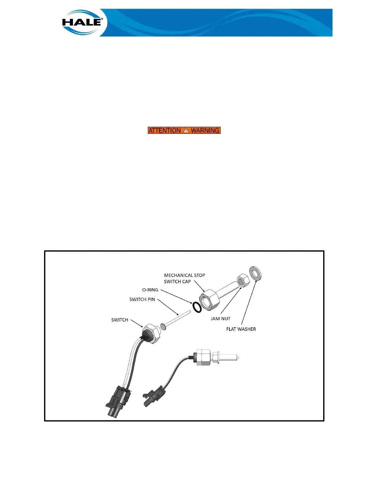
Figure 10. SWITCH PART IDENTIFICATION
8.
Loosen 3/8” lock nut from switch against gearbox
9.
Remove the switch cap that holds the switch assembly from the gearbox.
 Loading...