37
10.
Refer to Figure 10 to assemble new switch assembly from switch replacement kit.
11.
Operate the valve open then closed. The red indicator on the rocker switch or red indicator
on the manual placard is lit and the valve disc is in the closed position.
12.
Tighten the switch until it just touches the segment gear, then back out ½ to ¾ turn. Lock
in place with locknut.
13.
Operate the valve open then closed. See that the motor stops electrically and not against
the mechanical stop. When the motor stops operating, the handwheel should be able to
rotate about ¾ turn before stopping against mechanical stop. If not, back out switch cap
another ¼ turn and repeat step.
14.
Operate the valve to the open position. See that motor stops, the green lamp is lit and
valve disc is in the open position.
15.
Tighten the mechanical stop until it just touches the segment gear, then back out ½ to ¾
turn. Lock in place.
16.
Connect the wiring harness and turn power on to illuminate panel placard lights.
17.
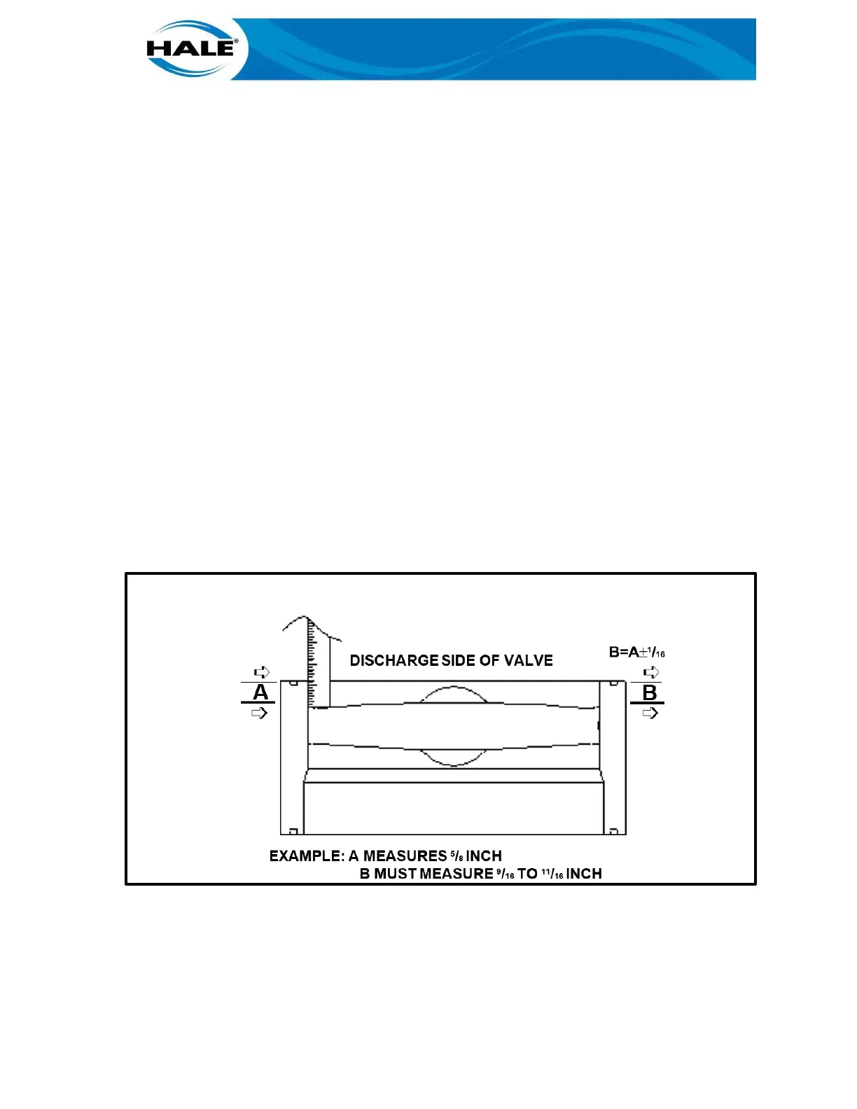
Manually close valve. Using a reference point, such as the valve body mounting surface,
measure the disc position. Refer to figure 10, the valve disc edge should be an equal dis-
tance from this reference point. The valve disc is now centered in the valve body in the
closed position.
NOTE
THE GEARBOX ADAPTER HAS OVERSIZED MOUNTING HOLES THAT ALLOW SOME AD-
JUSTMENT TO BE MADE TO SET THE TIMING OF THE CLOSED LIGHT/MOTOR OPERA-
TION VERSUS DISC POSITION.
Figure 11. DISC POSITION MEASUREMENT
18.
Slightly loosen the two 7/16-14 x 1-inch long counterbore screws that hold the gearbox
adapter to the valve body.
19.
Manually turn back gearbox handwheel a small amount until gearbox and gearbox adapter
are free to move. Find the mid position of this free play and tighten the two mounting screws.
20.
Operate the valve to the open position, then:
 Loading...