COMCO IKARUS
Maintenance Manual C42 Series
MaintenanceManual C42-
Series_Issue_VII_18.02.2014.doc
Revison No.:1 28 from 107
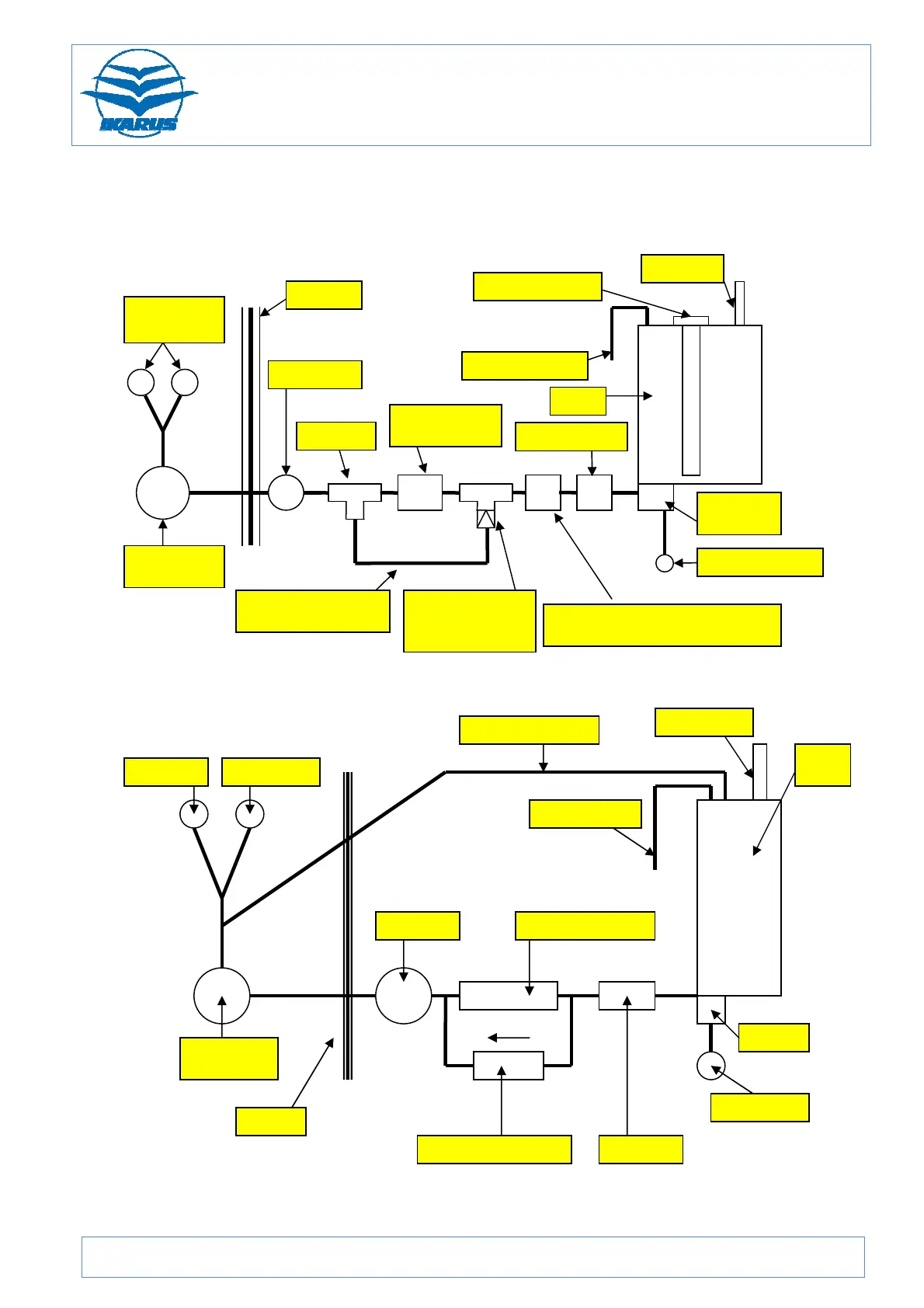
2.6 Fuel system
Figure 27: Schematic diagram of the fuel system C42 / C42B
Figure 28: Schematic diagram of the fuel system C42 UK / C42B UK / C42E
Mechanical
Fuel
Vapour return line
Filler nozzle
right and left
carburettor
mechanical
fuel tank
electrical fuel
electrical fuel pump
T fitting with
screwed-in
restriction valve
flow sensor for CAT fuel computer
 Loading...