COMCO IKARUS
Maintenance Manual C42 Series
MaintenanceManual C42-
Series_Issue_VII_18.02.2014.doc
Revison No.:1 83 from 107
5.2.1 Fuselage
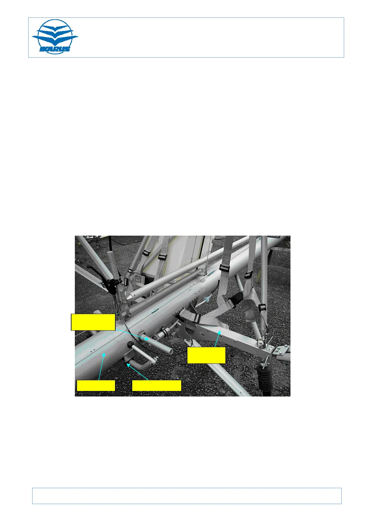
A 165 mm diameter aluminium tube runs from nose to tail and carries all the major
assemblies: engine, seats, undercarriage, fuel tank, and tail empennage. The
cockpit structure, consisting of a thin walled aluminium tube frame, includes a welded
aluminium box-section frame at its top to which the wing spars’ roots attach, and
which provides compression load carry-through for both spars.
The composite seats are supported around their edges by attachment to the cockpit
frame. Around the outboard edges of the seats, some of these loads are passed via
the composite lower fairing to a lateral beam consisting of a 56mm reinforced box
section. The ends of this beam accommodate the wing struts and withstand tension
loads from them.
All load carrying (structural) members of the airframe are aluminium alloy tubes; most
of which terminate in spherical bearings.
Figure 77: Main fuselage tube
Seat
Main cross
 Loading...