EasyManua.ls Logo

Inovance AM600-4AD User Manual

Inovance AM600-4AD
133 pages
To Next Page IconTo Next Page
To Previous Page IconTo Previous Page
Page #125 background imageLoading...
Page #125 background image
-124-
Introduction
7.1 Running and Stop
After the program is written into the CPU module
,
perform the following steps to start or stop the sys-
tem.
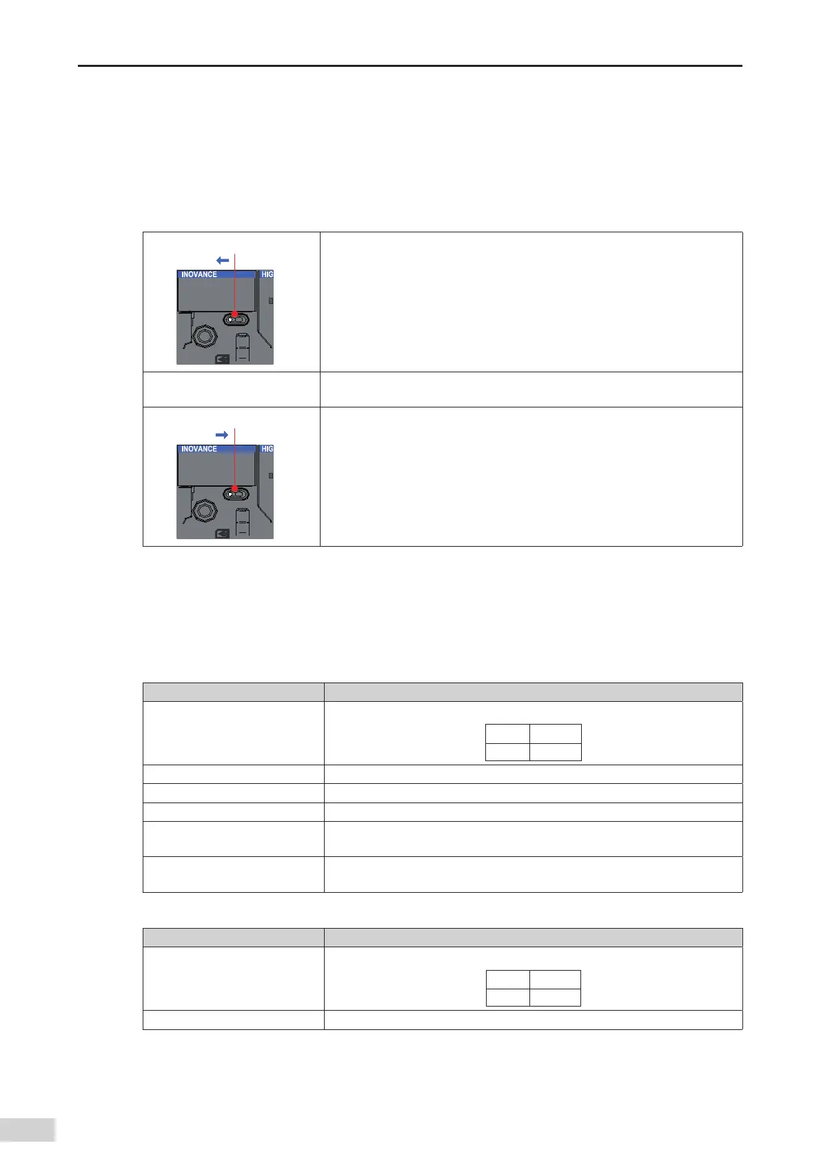
After the program is written into the CPU module when the CPU module is in STOP state
,
perform the
following steps to start the system:
.',
36/
4501
4XJUDIUP36/
1. Set the RUN/STOP switch to RUN.
2. Ensure that the RUN indicator remains on (green).
.',
36/
4501
4XJUDIUP4501
3. To stop the system
,
set the RUN/STOP switch to STOP. You can also stop the
system in the commissioning software of the host computer.
7.2 Indicators and MFK Button
7.2.1 LED Fault Indicators
1) CPU module indicators
Indicator Name Meaning
RUN
Indicates the current running status (RUN or STOP) of the system.
O󶍽 Stop
On Running
ERR Indicates that a system fault occurs.
SF Indicates that a system error occurs.
BF Indicates that a bus error occurs.
CANRUN
Indicates the CANopen/CANlink running status and complies with the CANopen
DS303 indicator standard.
CANERR
Indicates that a CANopen/CANlink error occurs and complies with the CANopen
DS303 indicator standard.
2) Analog I/O module indicators
Indicator Name Meaning
RUN
Indicates the current running status (RUN or STOP) of the system.
O󶍽 Stop
On Running
ERR Indicates that a module fault occurs.

Table of Contents

Question and Answer IconNeed help?

Do you have a question about the Inovance AM600-4AD and is the answer not in the manual?

Inovance AM600-4AD Specifications

General IconGeneral
Number of Channels4
Resolution16-bit
Power Supply24V DC
Protection ClassIP20
Input TypeAnalog
Voltage Input Range-10V ~ +10V
Current Input Range0-20mA, 4-20mA
Digital InputsDepends on configuration
Digital OutputsDepends on configuration
Analog OutputsDepends on configuration
Communication PortsEthernet, RS485, RS232

Summary

Chapter 1 Safety Instructions

Safety Instructions

General safety guidelines and precautions for using the product.

Chapter 2 Product Information

2.1.1 Functions of the CPU Module

Details the functions and specifications of the CPU module.

2.1.2 Functions of Local Expansion Modules

Explains the capabilities of local expansion modules.

2.1.3 Functions of Remote Expansion Modules

Explains the capabilities of remote expansion modules.

Chapter 3 Specifications

3.2 Hardware Performance Indicators of the CPU Module

Lists key performance metrics for the CPU module.

3.3 Specifications of the Power Module

Details the technical specifications of the power module.

3.5 Remote Expansion Module (EtherCAT)

Specifications for EtherCAT remote expansion modules.

3.6 Remote Expansion Module (Profibus-DP)

Specifications for Profibus-DP remote expansion modules.

3.7 Remote Expansion Module (CANopen)

Specifications for CANopen remote expansion modules.

Chapter 4 Installation

4.2 Installation Method

Describes the procedures for installing AM600 modules.

4.2.1 Module Installation Process

Outlines the sequence of steps for installing modules.

4.2.3 Connecting the Power Module, CPU Module, and Expansion Module

Explains how to connect the main AM600 system modules.

4.2.4 Mounting the Connected Module Group to the Guide Rail

Describes mounting the assembled modules onto the guide rail.

4.5 Replacing Modules

Steps for safely replacing installed modules.

Chapter 5 Wiring

5.1.1 Grounding Requirements

Details the grounding requirements for the system.

5.3 Wiring of the Power Module

Details wiring procedures for the power module.

5.3.3 Grounding

Details grounding requirements for the power module.

5.4 High-speed I/O Wiring of the CPU Module

Wiring instructions for the CPU module's high-speed I/O.

5.5 Communication Wiring of the CPU Module

Wiring instructions for CPU module communication ports.

5.5.2 Connection Through the EtherCAT Bus

Details how to connect via the EtherCAT bus.

5.5.3 Connection Through the Profibus-DP Bus

Details how to connect via the Profibus-DP bus.

5.5.4 Connection Through the CANopen/CANlink Bus

Details how to connect via the CANopen/CANlink bus.

5.5.5 Serial Communication Connection Through RS485

Details how to connect via RS485 serial communication.

5.5.6 Monitoring Connection Through Ethernet

Details how to connect via Ethernet for monitoring.

Related product manuals