-74-
Introduction
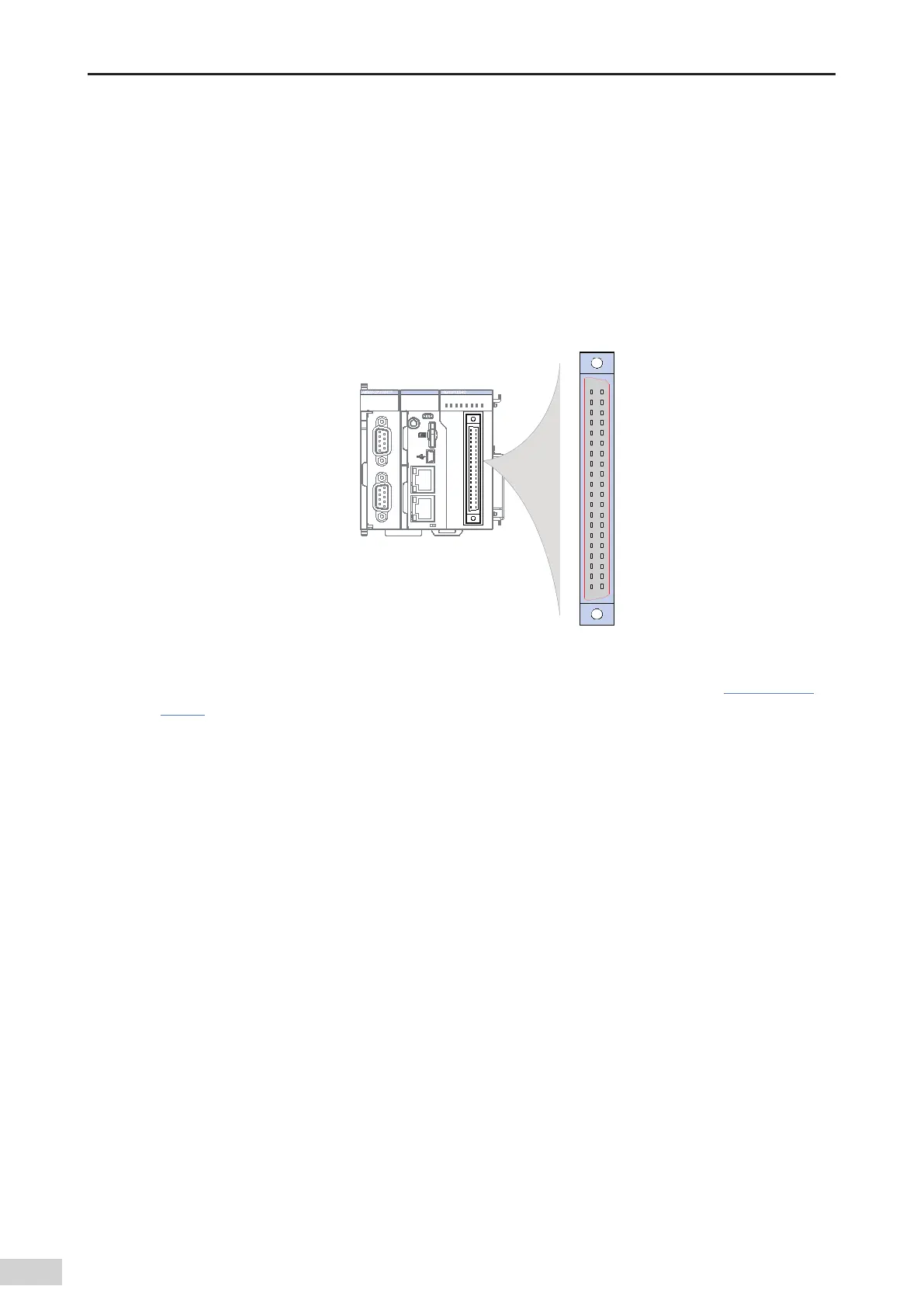
5.4 High-speed I/O Wiring of the CPU Module
5.4.1 Terminal Signal Arrangement
The AM600/610 CPU modules support high-speed I/O. They provide a high-density port which supports
16-channel high-speed input (the rst 6 channels support 24 V single-end input or dierential input and
the last 10 channels support 24 V single-end input) and 8-channel high-speed output.
The following gure shows the high-density port (silkscreen: CN5):
II
I
0 1 2 3 7654
30 1 4 5 6 72
4 5 6 73210
RUN
ERR
SF
BF
CANRUN
CANERR
RUN STOP
CN4 EtherCATCN3 EtherNET
CN2 CANCN1 RS485
CN5
12
40 39
MFK
40
39
2 1
CN5
Figure 5-12 Wiring terminal denitions of the CPU module
For the requirements on the internal circuit and external wiring of the port
,
see Section
"5.4.3 External
Wiring"
. Ensure that the wiring meets the corresponding requirements.
5.4.2 Wiring Precautions
1) The total extended distance of the extension cable of the high-speed I/O interface must be less than
3.0 m.
2) Avoid binding extension cables with cables that generate strong interference
,
for example
,
power
cables (high voltage and current)
,
and avoid laying extension cables parallelly with the preceding
cables.
3) Use the recommended cables and adapter board. You are advised to use shielded cables as
extension cables to improve the interference resistance capability.
4) When laying extension cables
,
ensure that the turning radius is greater than 76 mm. Otherwise
,
malfunction may occur due to performance deterioration and cable break.
 Loading...