-88-
Introduction
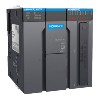
OPEF
4IJFMEMBZFSVODPOOFDUFE
$(/%VODPOOFDUFE
OPEF
a multi-core unshielded cable b shielded twisted pair
Figure 5-33 Terminal wiring
2) Method 1: Check whether other terminals of the node share a reference ground with the 485 circuit.
If yes
,
connect the CGND cable (shield layer) of the bus to the corresponding pin;
3) Method 2: Find the reference ground of the 485 circuit on the board of the node and connect a cable
from the reference ground to CGND or the shield layer;
4) Method 3: If you cannot nd the reference ground of the 485 circuit
,
keep the CGND cable or shield
layer unconnected
,
as shown in the preceding gure
,
and use an additional ground cable to connect
the node to the PE terminal of other nodes.
■
Transmission distance and number of nodes
The maximum node count and transmission distance supported by the standard 485 circuit at dierent
transmission rates are as follows:
No. Transmission Rate Transmission Distance Number of Nodes Cable Diameter
1 115.2 kbps 100 m 128 AWG26
2 19.2 kbps 1000 m 128 AWG26
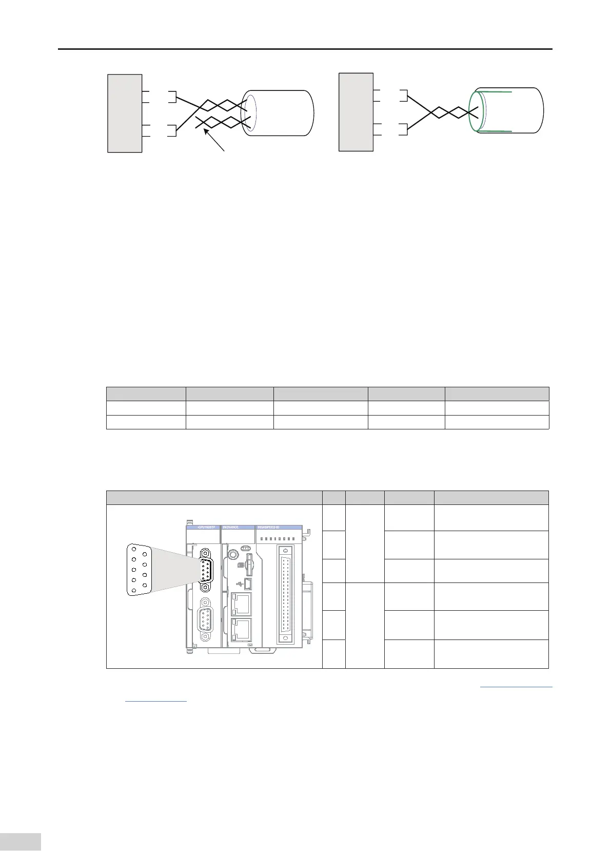
5) Communication port introduction
As shown in the following gure
,
CN1 is the RS485 port
,
which supports two channels of RS485 ports.
The two RS485 channels share a DB9 interface. The signal arrangement is as follows:
RS485 Port of the CPU Module Pin Channel Denition Function
II
I
0 1 2 3 7654
30 1 4 5 6 72
4 5 6 73210
RUN
ERR
SF
BF
CANRUN
CANERR
RUN STOP
CN4 EtherCATCN3 EtherNET
CN2 CANCN1 RS485
CN5
12
40 39
MFK
1
2
5
4
3
6
7
8
9
1
COM0
(RS485)
RS485-
Negative signal of the RS485
dierential pair of COM0
2 RS485+
Positive signal of the RS485
dierential pair of COM0
5 GND0 Power ground of COM0
6
COM1
(RS485)
RS485-
Negative signal of the RS485
dierential pair of COM1
9 RS485+
Positive signal of the RS485
dierential pair of COM1
3 GND1 Power ground of COM1
6) Wiring (including cable preparation and wiring description. For details
,
see Section
"5.2 Selecting and
Making Cables"
.)
5.5.6 Monitoring Connection Through Ethernet
1) Networking diagram
The Ethernet port of the CPU module can establish point-to-point connections to the PC and HMI
through an Ethernet cable.
 Loading...