Chapter 3 Mechanical and Electrical Installation
- 36 -
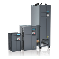
Figure 3-19 Parallel connection of DI terminals in SINK mode
0V
DI
1
OP
+24
V
+24V
2.4k
3.3Ω
NPN
Signal
External controller
Control board of AC drive 2
+VCC
COM
DI1
OP
+24V
2.4k
Control board of AC drive 1
COM
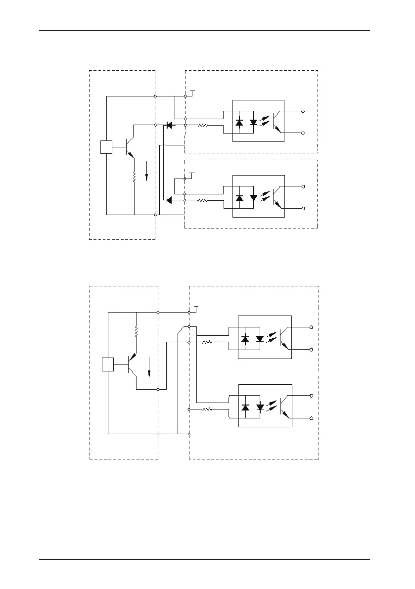
2. SOURCE wiring
Figure 3-20 SOURCE wiring mode
0V
DI5
DI1
OP
+24
V
+24V
2.4k
2.4k
3.3Ω
PNP
Signal
External controller AC drive control board
+VCC
COM
To use the SOURCE wiring mode, remove the jumper between the +24V and the OP terminals. Connect +24V
to the common port of the external controller, and connect the OP terminal to the COM terminal. If you intend to
use an external power supply with the SOURCE wiring mode, remove the jumper between the +24V and the OP
terminals. Connect the external power 0V to the OP terminal, and the positive side of the external power +24V to
the corresponding DI terminal via the contact on the external controller.
 Loading...