- 19 -
3 Hardware Connection
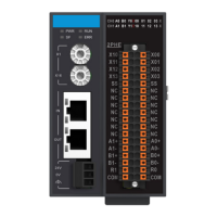
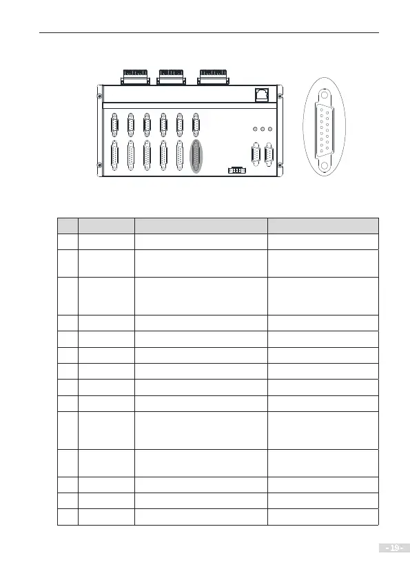
3.4 Description and Wiring of Pulse Control Output Interface
AXIS
1
2
3
4
5
6
7
8
9
10
11
12
13
14
15
Table 3-4 Denition of pulse control output interface
Pin Signal Description Electrical Specications
1 OVCC Internal 24 V output -
2 ALM
Servo/Stepper drive alarm signal
input
Optocoupler input,
isolation
3 SON Servo on
Optocoupler output,
isolation, equivalent OC
gate
4 DGND Digital ground -
5 DIR+/CCW+ Pulse direction dierential signal RS422 dierential output
6 DGND Digital ground -
7 CW+ Pulse dierential signal RS422 dierential output
8 Reserved - -
9 OGND Internal 24 V ground -
10 RESET Controller output reset signal
Optocoupler output,
isolation, equivalent OC
gate
11 SERDY Motor limit signal
Optocoupler input,
isolation
12 5V Internal 5 V output -
13 DIR -/CCW- Pulse direction dierential signal RS422 dierential output
14 PULSE-/CW- Pulse dierential signal RS422 dierential output
 Loading...