- 31 -
3 Hardware Connection
3.9 Wiring of Control Modes
The IMC30G-E series motion control card and the IMC30-6G axis control module used
together support network (EtherCAT) control, pulse control, and network and pulse
hybrid control, and implement control on EtherCAT stepper drive, servo drive, and
six local axes (pulse axes). This document describes the wiring of the pulse control
mode.
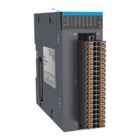
The IMC30-6G axis control module provides the pulse output control interface,
encoder input interface, and special I/O signal (including alarm signal, motor limit
signal, enable signal, alarm reset/clear signal). The pulse output signal and special I/
O signal are integrated into DB15 terminal.
The pulse signal/ encoder signal is dierential signal and complies with the RS422
physical layer standard, and can directly drive the RS422 compliant receiver or
dierential optocoupler receiving circuit. Adjust the wiring of the stepper drive of
single-ended optocoupler according to actual requirements. Sections 3.9.1 and 3.9.2
shows dierent wiring methods for dierent drives.
Prepare the cables for connecting the axis signal interface (AXIS0-AXIS5) and
encoder signal interface (ENC0-ENC5) to the drive or encoder according to actual
requirements. You can also purchase these cables from Inovance. For cable selection,
refer to
"1.5 Product Models"
.
 Loading...