T
Tonya MoranAug 5, 2025
What to do if Inovance ISMG Servo Drives LED display is not on?
- PPeter WhiteAug 5, 2025
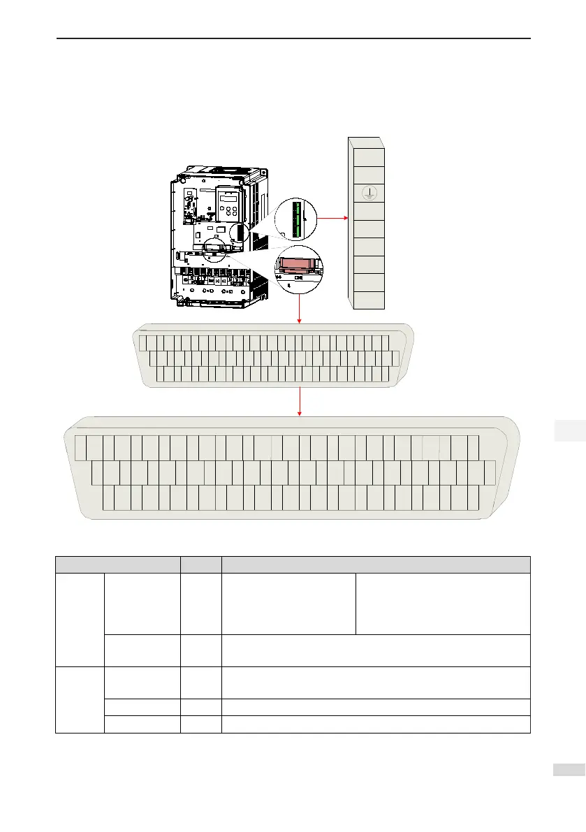
If the Inovance Servo Drives LED display is not on, there could be several reasons: 1. The control power voltage may be abnormal. Disconnect CN1, CN2, CN3, and CN4, and then measure the AC voltage between L1C and L2C. 2. The main power voltage may be abnormal. For single-phase 220 V models, measure the AC voltage between L1 and L2. If the DC bus voltage amplitude (voltage between P and -) is lower than 200 V, "nrd" will be displayed. For three-phase 220/380 V models, measure the AC voltage between R, S, and T. If the DC bus voltage amplitude (voltage between P and -) is lower than 460 V, "nrd" will be displayed. 3. The program burning terminal may be shorted. Check the program burning terminal to ensure it is not shorted.